ASRock ConRoe865PE User Manual - Page 9
Dual Channel A: DDR1, DDR3; Blue - socket 775 motherboard
 |
View all ASRock ConRoe865PE manuals
Add to My Manuals
Save this manual to your list of manuals |
Page 9 highlights
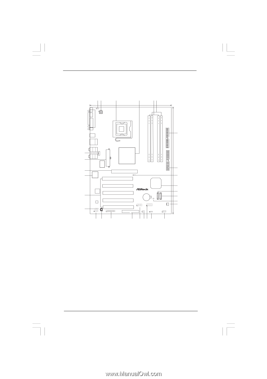
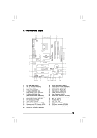
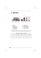
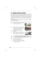
1.3 Motherboard Layout 12 PS2 Mouse 1 PS2_USB_PWR1 ATX12V1 3 4 22.9cm (9.0 in) 56 PARALLEL PORT PS2 Keyboard Presler Conroe COM1 DDR3 (64/72 bit, 184-pin module) DDR4 (64/72 bit, 184-pin module) DDR1 (64/72 bit, 184-pin module) DDR2 (64/72 bit, 184-pin module) USB 2.0 T: USB2 B: USB3 USB 2.0 T: USB0 B: USB1 Top: RJ-45 FSB1066 Dual Core CPU Dual Channel DDR400 Top: REAR SPK Center: SIDE SPK Bottom: CTR BASS CPU_FAN1 29 28 27 26 25 24 Top: LINE IN Center: FRONT Bottom: MIC IN ATXPWR1 Intel 865PE/865G Chipset Super IO 4Mb BIOS PCI LAN AUDIO CODEC JR1 JL1 1 AUDIO1 CD1 AGP 8X 1.5V_AGP1 PCI 1 1 FSB1 7.1CH PCI 2 ConRoe865PE PCI 3 PCI 4 PCI 5 GAME1 FLOPPY1 Intel ICH5 ` RoHS 1 USB45 CMOS Battery CLRCMOS0 SATA1 SATA2 USB2.0 1 USB67 SATA 1 IR1 1 SPEAKER1 PANEL 1 PLED PWRBTN 1 HDLED RESET 23 22 21 20 19 1817 16 15 CHA_FAN1 IDE1 IDE2 30.5cm (12.0 in) 7 8 9 10 11 12 13 14 1 PS2_USB_PWR1 Jumper 2 ATX 12V Connector (ATX12V1) 3 775-Pin CPU Socket 4 North Bridge Controller 5 2 x 184-pin DDR DIMM Slots (Dual Channel A: DDR1, DDR3; Blue) 6 2 x 184-pin DDR DIMM Slots (Dual Channel B: DDR2, DDR4; Black) 7 Secondary IDE Connector (IDE2, Black) 8 Primary IDE Connector (IDE1, Blue) 9 FSB Select Jumper (FSB1) 10 South Bridge Controller 11 Primary Serial ATA Connector (SATA1) 12 Secondary Serial ATA Connector (SATA2) 13 Clear CMOS Jumper (CLRCMOS0) 14 Chassis Fan Connector (CHA_FAN1) 15 System Panel Header (PANEL1) 16 Chassis Speaker Header (SPEAKER 1) 17 USB 2.0 Header (USB67, Blue) 18 Infrared Module Header (IR1) 19 USB 2.0 Header (USB45, Blue) 20 Floppy Connector (FLOPPY1) 21 Game Connector (GAME1) 22 Internal Audio Connector: CD1 (Black) 23 Front Panel Audio Header (AUDIO1) 24 JR1 / JL1 Jumpers 25 PCI Slots (PCI1- 5) 26 BIOS FWH Chip 27 AGP Slot (1.5V_AGP1) 28 ATX Power Connector (ATXPWR1) 29 CPU Fan Connector (CPU_FAN1) 9
-
 1
1 -
2
-
3
-
 4
4 -
 5
5 -
 6
6 -
 7
7 -
 8
8 -
 9
9 -
 10
10 -
 11
11 -
 12
12 -
 13
13 -
 14
14 -
15
-
16
-
17
-
18
-
19
-
20
-
21
-
22
-
23
-
24
-
25
-
26
-
27
-
28
-
29
-
30
-
31
-
32
-
33
-
34
-
35
-
36
-
37
-
38
-
39
 |
 |