ASRock FM2A88X-ITX User Manual - Page 27
Expansion Slots PCI Express Slots - + wifi
 |
View all ASRock FM2A88X-ITX manuals
Add to My Manuals
Save this manual to your list of manuals |
Page 27 highlights
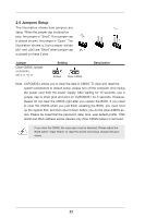
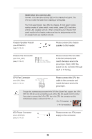
2.4 Expansion Slots (PCI Express Slots) There is 1 PCI Express slot and 1 half/full (mSATA) mini-PCI Express slot on this motherboard. Before installing an expansion card, please make sure that the power supply is switched off or the power cord is unplugged. Please read the documentation of the expansion card and make necessary hardware settings for the card before you start the installation. PCIE Slots: PCIE1 (PCIe 3.0 x16 slot) is used for PCI Express x16 lane width graphics cards. MINI_PCIE1 (mSATA) (half/full (mSATA) mini-PCI Express slot) is used for mSATA or mini-PCIe module. Please uninstall the screw knob counterclockwise and move it to NUT1 if you are using an mSATA or full size mini-PCIe module. You may keep the screw knob installed at NUT2 if you are using a WiFi module or half size mini-PCIe module. (See Page 13 for NUT1 and NUT2.) 22
-
 1
1 -
2
-
3
-
4
-
5
-
6
-
7
-
8
-
9
-
10
-
11
-
12
-
13
-
14
-
15
-
16
-
17
-
18
-
19
-
20
-
21
-
 22
22 -
 23
23 -
 24
24 -
 25
25 -
 26
26 -
 27
27 -
 28
28 -
 29
29 -
 30
30 -
 31
31 -
 32
32 -
33
-
34
-
35
-
36
-
37
-
38
-
39
-
40
-
41
-
42
-
43
-
44
-
45
-
46
-
47
-
48
-
49
-
50
-
51
-
52
-
53
-
54
-
55
-
56
-
57
-
58
-
59
-
60
-
61
-
62
-
63
-
64
-
65
-
66
-
67
-
68
-
69
-
70
-
71
-
72
-
73
-
74
-
75
 |
 |
