ASRock Fatal1ty 990FX Professional User Manual - Page 38
Smart Switches, Rear USB 3.0 Bracket Installation Guide
 |
View all ASRock Fatal1ty 990FX Professional manuals
Add to My Manuals
Save this manual to your list of manuals |
Page 38 highlights
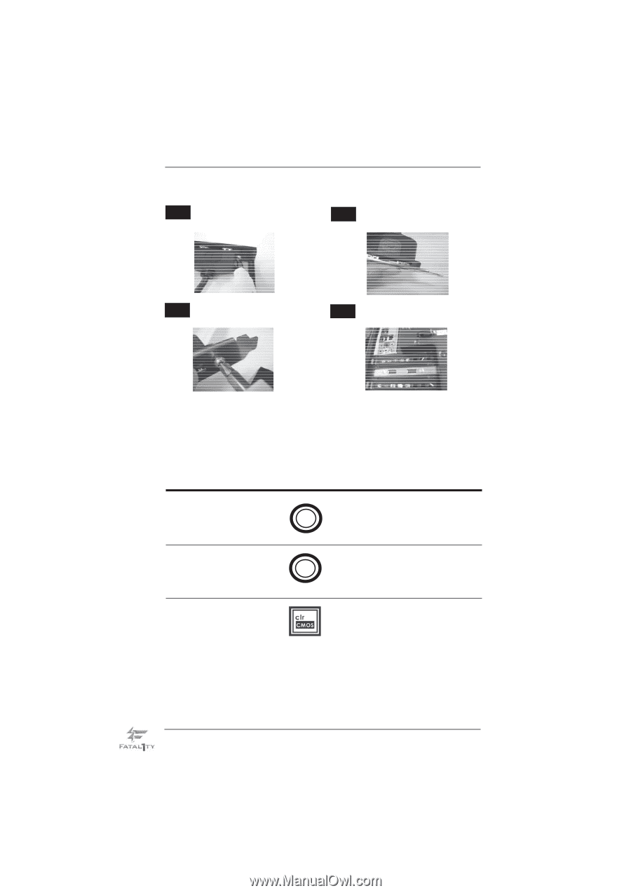
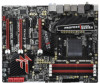
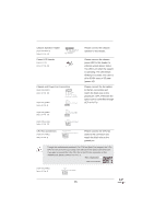
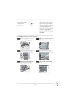
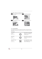
Rear USB 3.0 Bracket Installation Guide Step 1 Unscrew the two screws from the Front Step 2 Put the USB 3.0 cable and the USB 3.0 Panel. rear USB 3.0 bracket together. Step 3 Screw the two screws into the rear USB 3.0 bracket. Step 4 Put the rear USB 3.0 bracket into the chassis. 2.10 Smart Switches This motherboard has three smart switches: power switch, reset switch and clear CMOS switch, allowing users to quickly turn on/off or reset the system or clear the CMOS values. Power Switch (PWRBTN) (see p.14 No. 22) Power Power Switch is a smart switch, allowing users to quickly turn on/off the system. Reset Switch (RSTBTN) (see p.14 No. 21) Reset Switch is a smart switch, Reset allowing users to quickly reset the system. Clear CMOS Switch (CLRCBTN) (see p.15 No. 20) Clear CMOS Switch is a smart switch, allowing users to quickly clear the CMOS values 38
-
 1
1 -
2
-
3
-
4
-
5
-
6
-
7
-
8
-
9
-
10
-
11
-
12
-
13
-
14
-
15
-
16
-
17
-
18
-
19
-
20
-
21
-
22
-
23
-
24
-
25
-
26
-
27
-
28
-
29
-
30
-
31
-
32
-
 33
33 -
 34
34 -
 35
35 -
 36
36 -
 37
37 -
 38
38 -
 39
39 -
 40
40 -
 41
41 -
 42
42 -
 43
43 -
44
-
45
-
46
-
47
-
48
-
49
-
50
-
51
-
52
-
53
-
54
-
55
-
56
-
57
-
58
-
59
-
60
-
61
-
62
-
63
-
64
-
65
-
66
-
67
-
68
-
69
-
70
-
71
-
72
-
73
-
74
-
75
 |
 |