ASRock Fatal1ty 990FX Professional User Manual - Page 9
Rear Panel I/O, CAUTION 6, SATA3, USB 3.0, Connector, Smart Switch, BIOS Feature - atx
 |
View all ASRock Fatal1ty 990FX Professional manuals
Add to My Manuals
Save this manual to your list of manuals |
Page 9 highlights
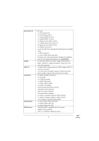
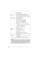
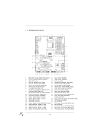
Rear Panel I/O SATA3 USB 3.0 Connector Smart Switch BIOS Feature I/O Panel - 1 x PS/2 Mouse Port - 1 x PS/2 Keyboard Port - 1 x Coaxial SPDIF Out Port - 1 x Optical SPDIF Out Port - 5 x Ready-to-Use USB 2.0 Ports - 1 x Fatal1ty Mouse Port (USB 2.0) - 2 x Ready-to-Use USB 3.0 Ports - 2 x eSATA3 Connectors - 2 x RJ-45 LAN Ports with LED (ACT/LINK LED and SPEED LED) - 1 x IEEE 1394 Port - 1 x Clear CMOS Switch with LED - HD Audio Jack: Side Speaker/Rear Speaker/Central/Bass/ Line in/Front Speaker/Microphone (see CAUTION 6) - 6 x SATA3 6.0 Gb/s connectors, support RAID (RAID 0, RAID 1, RAID 0+1, JBOD and RAID 5), NCQ, AHCI and "Hot Plug" functions - 2 x Rear USB 3.0 ports by Etron EJ168A, support USB 1.0 /2.0/3.0 up to 5Gb/s - 2 x Front USB 3.0 headers (support 4 USB 3.0 ports) by Etron EJ168A, support USB 1.0/2.0/3.0 up to 5Gb/s - 6 x SATA3 6.0Gb/s connectors - 1 x IR header - 1 x COM port header - 1 x IEEE 1394 header - 1 x HDMI_SPDIF header - 1 x Power LED header - CPU/Chassis/Power FAN connector - 24 pin ATX power connector - 8 pin 12V power connector - Front panel audio connector - 2 x USB 2.0 headers (support 4 USB 2.0 ports) - 2 x USB 3.0 headers (support 4 USB 3.0 ports) - 1 x Dr. Debug (7-Segment Debug LED) - 1 x Clear CMOS Switch with LED - 1 x Power Switch with LED - 1 x Reset Switch with LED - 32Mb AMI UEFI Legal BIOS with GUI support - Supports "Plug and Play" - ACPI 1.1 Compliance Wake Up Events 9
-
 1
1 -
2
-
3
-
 4
4 -
 5
5 -
 6
6 -
 7
7 -
 8
8 -
 9
9 -
 10
10 -
 11
11 -
 12
12 -
 13
13 -
 14
14 -
15
-
16
-
17
-
18
-
19
-
20
-
21
-
22
-
23
-
24
-
25
-
26
-
27
-
28
-
29
-
30
-
31
-
32
-
33
-
34
-
35
-
36
-
37
-
38
-
39
-
40
-
41
-
42
-
43
-
44
-
45
-
46
-
47
-
48
-
49
-
50
-
51
-
52
-
53
-
54
-
55
-
56
-
57
-
58
-
59
-
60
-
61
-
62
-
63
-
64
-
65
-
66
-
67
-
68
-
69
-
70
-
71
-
72
-
73
-
74
-
75
 |
 |