ASRock Fatal1ty Z97 Killer/3.1 User Manual - Page 40
Installation Procedure
 |
View all ASRock Fatal1ty Z97 Killer/3.1 manuals
Add to My Manuals
Save this manual to your list of manuals |
Page 40 highlights
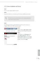
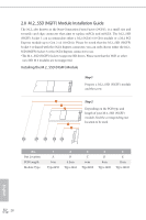
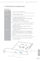
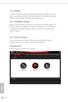
Installation Procedure he ASRock USB 3.1/A+C provides two external USB 3.1 ports which support transfer rates up to 10 Gbps. Follow the simple steps below to install the ASRock USB 3.1/A+C. Step 1 Power of the PC and unplug the power cord. Detach all other cables from the PC. Step 2 Remove the side panel from the computer case. *Refer to the documentation that comes with your PC for details. Step 3 Locate an available x4, x8 or x16 PCI Express slot on your motherboard and remove its slot bracket. *To maximize the performance of ASRock USB 3.1/A+C, it is highly recommended to insert the card into the PCIE2 (from CPU) if the slot is not occupied by graphics card. If the PCIE2 is occupied, insert the card into PCIE4 (from PCH). Step 4 Align the ASRock USB 3.1/A+C with the PCI Express slot and press down irmly until it is fully seated in the slot. hen secure the card with the slot bracket's holding screw. Step 5 Replace the side panel. Reconnect the power cord and any other cables that were disconnected. *Jumper Setup: Jumper J1 is set to Pin1-2 by default and allows device charging during S3 (Sleep), S4 (Suspend) or S5 (Power Of) power states. To disable device charging during S3/ S4/S5 (Power Of) power states, you need to move the jumper cap placed on Pin1-2 (default) to Pin2-3. *Please install driver for Windows® 7 (32-bit and 64-bit). 32 English
-
 1
1 -
2
-
3
-
4
-
5
-
6
-
7
-
8
-
9
-
10
-
11
-
12
-
13
-
14
-
15
-
16
-
17
-
18
-
19
-
20
-
21
-
22
-
23
-
24
-
25
-
26
-
27
-
28
-
29
-
30
-
31
-
32
-
33
-
34
-
 35
35 -
 36
36 -
 37
37 -
 38
38 -
 39
39 -
 40
40 -
 41
41 -
 42
42 -
 43
43 -
 44
44 -
 45
45 -
46
-
47
-
48
-
49
-
50
-
51
-
52
-
53
-
54
-
55
-
56
-
57
-
58
-
59
-
60
-
61
-
62
-
63
-
64
-
65
-
66
-
67
-
68
-
69
-
70
-
71
-
72
-
73
-
74
-
75
-
76
-
77
-
78
-
79
-
80
-
81
-
82
-
83
-
84
-
85
-
86
-
87
-
88
-
89
-
90
-
91
-
92
-
93
-
94
-
95
-
96
-
97
-
98
-
99
-
100
-
101
-
102
-
103
-
104
-
105
-
106
-
107
-
108
-
109
-
110
-
111
 |
 |
