ASRock H55M/USB3 R2.0 User Manual
ASRock H55M/USB3 R2.0 Manual
 |
View all ASRock H55M/USB3 R2.0 manuals
Add to My Manuals
Save this manual to your list of manuals |
ASRock H55M/USB3 R2.0 manual content summary:
- ASRock H55M/USB3 R2.0 | User Manual - Page 1
H55M/USB3 User Manual Version 2.0 Published May 2010 Copyright©2010 ASRock INC. All rights reserved. 1 - ASRock H55M/USB3 R2.0 | User Manual - Page 2
any form or by any means, except duplication of documentation by the purchaser for backup purpose, without written consent of ASRock Inc. Products and corporate names appearing in this manual may or may not be registered trademarks or copyrights of their respective companies, and are used only for - ASRock H55M/USB3 R2.0 | User Manual - Page 3
Disks Installation 27 2.12 Hot Plug Function for SATA / SATAII HDDs 27 2.13 SATA / SATAII HDD Hot Plug Feature and Operation Guide 28 2.14 Driver Installation Guide 30 2.15 Installing Windows® 7 / 7 64-bit / VistaTM / VistaTM 64-bit / XP / XP 64-bit Without RAID Functions 30 2.15.1 Installing - ASRock H55M/USB3 R2.0 | User Manual - Page 4
UTILITY 32 3.1 Introduction 32 3.1.1 BIOS Menu Bar 32 3.1.2 Navigation Keys 33 3.2 Main Screen 33 3.3 OC Tweaker 51 3.8 Exit Screen 52 4 Software Support 53 4.1 Install Operating System 53 4.2 Support CD Information 53 4.2.1 Running Support CD 53 4.2.2 Drivers Menu 53 4.2.3 Utilities - ASRock H55M/USB3 R2.0 | User Manual - Page 5
information about the model you are using. www.asrock.com/support/index.asp 1.1 Package Contents ASRock H55M/USB3 Motherboard (Micro ATX Form Factor: 9.6-in x 8.8-in, 24.4 cm x 22.4 cm) ASRock H55M/USB3 Quick Installation Guide ASRock H55M/USB3 Support CD 2 x Serial ATA (SATA) Data Cables (Optional - ASRock H55M/USB3 R2.0 | User Manual - Page 6
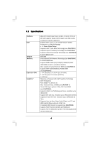
in LGA1156 Package - 4 + 1 Power Phase Design - Supports Intel® Turbo Boost Technology (see CAUTION 1) - Supports Hyper-Threading Technology (see CAUTION 2) - Supports Untied Overclocking Technology (see CAUTION 3) - Supports EM64T CPU - Intel® H55 - Dual Channel DDR3 Memory Technology (see CAUTION - ASRock H55M/USB3 R2.0 | User Manual - Page 7
8 pin 12V power connector - Front panel audio connector - 3 x USB 2.0 headers (support 6 USB 2.0 ports) (see CAUTION 12) - 64Mb AMI Legal BIOS - Supports "Plug and Play" - ACPI 1.1 Compliance Wake Up Events - Supports jumperfree - SMBIOS 2.3.1 Support - CPU VID, VCCM, SB, VTT, PCH PLL Voltage Multi - ASRock H55M/USB3 R2.0 | User Manual - Page 8
Support CD - Drivers, Utilities, AntiVirus Software (Trial Version), ASRock Software Suite (CyberLink DVD Suite - OEM and Trial; Creative Sound Blaster X-Fi MB - Trial) Unique Feature - ASRock , including adjusting the setting in the BIOS, applying Untied Overclocking Technology, or using - ASRock H55M/USB3 R2.0 | User Manual - Page 9
supports Dual Channel Memory Technology. Before you implement Dual Channel Memory Technology, make sure to read the installation guide of XP 64-bit / XP SP1 or SP2. 13. It is a user-friendly ASRock overclocking tool which allows you to surveil your system by hardware monitor function and overclock - ASRock H55M/USB3 R2.0 | User Manual - Page 10
or press key to BIOS setup menu to access ASRock Instant Flash. Just launch this tool and save the new BIOS file to your USB flash Cooler Option (C.C.O.) provides the flexible option to adopt two different CPU cooler types, Socket LGA 775 and LGA 1156. Please be noticed that not all the 775 CPU - ASRock H55M/USB3 R2.0 | User Manual - Page 11
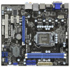
PHY 30 CMOS 29 PCIE2 Battery Intel Super I/O Gigabit LAN H55 12 SATAII_5 (Port 4) 28 27 AUDIO CODEC HD_AUDIO1 1 PCIE3 H55M/USB3 ErP/EuP Ready RoHS PCI1 IR1 1 LPT1 1 COM1 1 64Mb BIOS USB8_9 CLRCMOS1 1 1 USB10_11 SPEAKER1 1 CHA_FAN1 1 USB_PWR3 1 USB6_7 1 PLED PWRBTN - ASRock H55M/USB3 R2.0 | User Manual - Page 12
1.4 I/O Panel 1 2 34 58 69 7 10 16 15 1 USB 2.0 Ports (USB45) 2 VGA/D-Sub Port 3 USB 2.0 Ports (USB23) * 4 LAN RJ-45 Port 5 Central / Bass (Orange) 6 Rear Speaker (Black) 7 Optical SPDIF Out Port 8 Line In (Light Blue) 14 13 12 11 ** 9 Front Speaker (Lime) 10 Microphone (Pink) 11 USB 2.0 - ASRock H55M/USB3 R2.0 | User Manual - Page 13
Chapter 2: Installation This is a Micro ATX form factor (9.6" x 8.8", 24.4 x 22.4 cm) motherboard. Before you install the motherboard, study the configuration of your chassis to ensure that the motherboard fits into it. Make sure to unplug the power cord before installing or removing the motherboard - ASRock H55M/USB3 R2.0 | User Manual - Page 14
CPU, please follow the steps below. Load Plate Load Lever Contact Array Socket Body 1156-Pin Socket Overview Before you insert the 1156-Pin CPU into the socket, please check if the CPU surface is unclean or PnP cap. 2. This cap must be placed if returning the motherboard for after service. 14 - ASRock H55M/USB3 R2.0 | User Manual - Page 15
Heat Sink) up. Locate Pin1 and the two orientation key notches. orientation key notch alignment key Pin1 Pin1 orientation key notch 1156-Pin CPU alignment key 1156-Pin Socket For proper inserting, please ensure to match the two orientation key notches of the CPU with the two alignment keys - ASRock H55M/USB3 R2.0 | User Manual - Page 16
with fan operation or contact other components. Please be noticed that this motherboard supports Combo Cooler Option (C.C.O.), which provides the flexible option to adopt two different CPU cooler types, Socket LGA 775 and LGA 1156. The white throughholes are for Socket LGA 1156 CPU fan. 16 - ASRock H55M/USB3 R2.0 | User Manual - Page 17
2.5 Installation of Memory Modules (DIMM) H55M/USB3 motherboard provides two 240-pin DDR3 (Double Data Rate 3) DIMM slots, and supports Dual Channel Memory Technology. For dual channel configuration, you always need to install two identical (the same brand, speed, size and chip-type) memory modules - ASRock H55M/USB3 R2.0 | User Manual - Page 18
2.6 Expansion Slots (PCI and PCI Express Slots) There are 1 PCI slot and 3 PCI Express slots on this motherboard. PCI slot: PCI slot is used to install expansion cards that have the 32-bit PCI interface. PCIE slots: PCIE1 (PCIE x16 slot; Blue) is used for PCI Express x16 lane width graphics cards. - ASRock H55M/USB3 R2.0 | User Manual - Page 19
and pin3 on CLRCMOS1 for 5 seconds. However, please do not clear the CMOS right after you update the BIOS. If you need to clear the CMOS when you just finish updating the BIOS, you must boot up the system first, and then shut it down before you do the clearCMOS action. 19 - ASRock H55M/USB3 R2.0 | User Manual - Page 20
see p.11, No. 11) (SATAII_5 (Port 4): see p.11, No. 12) SATAII_2 (Port 1) SATAII_1 (Port 0) These five Serial ATAII (SATAII) connectors support SATA data cables for internal storage devices. The current SATAII interface allows up to 3.0 Gb/s data transfer rate. SATAII_3 (Port 2) SATAII_4 (Port - ASRock H55M/USB3 R2.0 | User Manual - Page 21
allows convenient connection and control of audio devices. 1. High Definition Audio supports Jack Sensing, but the panel wire on the chassis must support HDA to function correctly. Please follow the instruction in our manual and chassis manual to install your system. 2. If you use AC'97 audio panel - ASRock H55M/USB3 R2.0 | User Manual - Page 22
connect a CPU fan cable to this connector and match the black wire to the ground pin. 1 2 3 4 Though this motherboard provides 4-Pin CPU fan (Quiet Fan) support, the 3-Pin CPU fan still can work successfully even without the fan speed control function. If you plan to connect the 3-Pin CPU fan to - ASRock H55M/USB3 R2.0 | User Manual - Page 23
Pin 1 and Pin 5. 4 8 4-Pin ATX 12V Power Supply Installation 1 6 Serial port Header (9-pin COM1) RRXD1 DDTR#1 DDSR#1 CCTS#1 This COM1 header supports a serial port module. (see p.11 No.25) 1 RRI#1 RRTS#1 GND TTXD1 t DDCD#1 HDMI_SPDIF Header (3-pin HDMI_SPDIF1) (see p.11 No. 31) 1 GND - ASRock H55M/USB3 R2.0 | User Manual - Page 24
HDMI_SPDIF Cable (Optional) C B A Please connect the black end (A) of HDMI_SPDIF cable to the HDMI_SPDIF header on the motherboard. Then connect the white end (B or C) of HDMI_SPDIF cable to the HDMI_SPDIF connector of HDMI VGA card. A. black end B. white end (2-pin) C. white end (3-pin) +5V - ASRock H55M/USB3 R2.0 | User Manual - Page 25
. For the proper installation of HDMI VGA card, please refer to the installation guide on page 18. Step 2. Connect the black end (A) of HDMI_SPDIF cable to the of PCI Express VGA card. Please refer to the VGA card user manual for connector usage in advance. Connect the HDMI output connector on HDMI - ASRock H55M/USB3 R2.0 | User Manual - Page 26
please carefully read below SATAII hard disk setup guide. Some default setting of SATAII hard disks may not be at SATAII mode, which operate with the best performance. In order to enable SATAII function, please follow the below instruction with different vendors to correctly adjust your SATAII hard - ASRock H55M/USB3 R2.0 | User Manual - Page 27
) Hard Disks Installation This motherboard adopts Intel® H55 bridge chipset that supports Serial ATA (SATA) / Serial ATAII (SATAII) hard disks. You may install SATA / SATAII hard disks on this motherboard for internal storage devices. This section will guide you to install the SATA / SATAII hard - ASRock H55M/USB3 R2.0 | User Manual - Page 28
into system properly. The latest SATA / SATAII driver is available on our support website: www.asrock.com 4. Make sure to use the SATA power cable & data cable, which are from our motherboard package. 5. Please follow below instructions step by step to reduce the risk of HDD crash or data loss - ASRock H55M/USB3 R2.0 | User Manual - Page 29
the SATA / SATAII HDD. How to Hot Unplug a SATA / SATAII HDD: Points of attention, before you process the Hot Unplug: Please do follow below instruction sequence to process the Hot Unplug, improper procedure will cause the SATA / SATAII HDD damage and data loss. Step 1 Unplug SATA data cable from - ASRock H55M/USB3 R2.0 | User Manual - Page 30
HDDs without RAID functions, please follow below steps. AHCI mode is not supported under Windows® XP / XP 64-bit OS. Using SATA / SATAII HDDs without NCQ function (IDE mode) STEP 1: Set up BIOS. A. Enter BIOS SETUP UTILITY Advanced screen Storage Configuration. B. Set the option "SATA Operation Mode - ASRock H55M/USB3 R2.0 | User Manual - Page 31
motherboard supports Untied Overclocking Technology, which means during overclocking, FSB enjoys better margin due to fixed PCI / PCIE buses. Before you enable Untied Overclocking function, please enter "Overclock Mode" option of BIOS setup to set the selection from [Auto] to [Manual]. Therefore - ASRock H55M/USB3 R2.0 | User Manual - Page 32
default system device to locate and load the Operating System Security To set up the security features Exit To exit the current screen or the BIOS SETUP UTILITY Use < > key or < > key to choose among the selections on the menu bar, and then press to get into the sub screen - ASRock H55M/USB3 R2.0 | User Manual - Page 33
OC Tweaker Advanced H/W Monitor Boot Security Exit System Overview System Time System Date [14:00:09] [Fri 03/05/2010] BIOS Version : H55M/USB3 P1.00 Processor Type : Intel (R) Core (TM) CPU 870 @ 2.93GHz (64bit) Processor Speed : 2933MHz Microcode Update : 106E5/3 Cache Size : 8192KB - ASRock H55M/USB3 R2.0 | User Manual - Page 34
In the OC Tweaker screen, you can set up overclocking features. BIOS SETUP UTILITY Main OC Tweaker Advanced H/W Monitor Boot Security Exit OC this function, please set this item to [Enabled]. Besides the BIOS option, you can also choose our Intelligent Energy Saver utility to enable this function. - ASRock H55M/USB3 R2.0 | User Manual - Page 35
state. The default value is [Disabled]. Overclock Mode Use this to select Overclock Mode. Configuration options: [Auto], [Manual], [I.O.T.] and [Optimized]. The default value is [Auto]. If you select [Manual], Untied Overclocking function is enabled. Please refer to page 31 for the details of Untied - ASRock H55M/USB3 R2.0 | User Manual - Page 36
Timing Control DRAM tCL DRAM tRCD DRAM tRP DRAM tRAS DRAM tRFC DRAM tWR DRAM tWTR DRAM tRRD DRAM tRTP DRAM tFAW DRAM Command Rate BIOS SETUP UTILITY 9 [Auto] 9 [Auto] 9 [Auto] 24 [Auto] 74 [Auto] 10 [Auto] 5 [Auto] 4 [Auto] 5 [Auto] 20 [Auto] [Auto] DRAM tCL Min = 6 Max = 11 +F1 F9 F10 - ASRock H55M/USB3 R2.0 | User Manual - Page 37
VDroop Control Use this to enable or disable ASRock VDroop control. Configuration options: [With VDroop] and [Without VDroop]. The default value is [With VDroop]. CPU Voltage Use this to select CPU Voltage. Configuration options: [Auto], [Manual] and [Overdrive Offset]. The default value is [Auto - ASRock H55M/USB3 R2.0 | User Manual - Page 38
cause system to malfunction. CPU Configuration Chipset Configuration ACPI Configuration Storage Configuration PCIPnP Configuration SuperIO Configuration USB Configuration BIOS Update Utility ASRock Instant Flash Select Screen Select Item Enter Go to Sub Screen F1 General Help F9 Load Defaults F10 - ASRock H55M/USB3 R2.0 | User Manual - Page 39
3.4.1CPU Configuration BIOS SETUP UTILITY Advanced Configure advanded CPU settings Intel (R) Core (TM) CPU Halt State All processors support the Halt State (C1). The C1 state is supported through the native processor instructions HLT and MWAIT and requires no hardware support from the chipset. In - ASRock H55M/USB3 R2.0 | User Manual - Page 40
® VistaTM and want to enable this function, please set this item to [Enabled]. This item will be hidden if the current CPU does not support Intel (R) SpeedStep(tm) tech.. Please note that enabling this function may reduce CPU voltage and lead to system stability or compatibility issue with some - ASRock H55M/USB3 R2.0 | User Manual - Page 41
3.4.2Chipset Configuration BIOS SETUP UTILITY Advanced Chipset Settings Primary Graphics Adapter Share Memory DVMT Mode Select DVMT/FIXED Memory Onboard HD Audio Front Panel OnBoard HDMI HD Audio - ASRock H55M/USB3 R2.0 | User Manual - Page 42
OnBoard Lan This allows you to enable or disable the "OnBoard Lan" feature. Intel VT-d Configuration Use this to enable or disable Intel® VT-d technology (Intel® Virtualization Technology for Directed I/O). The default value of this feature is [Disabled]. 42 - ASRock H55M/USB3 R2.0 | User Manual - Page 43
3.4.3 ACPI Configuration BIOS SETUP UTILITY Advanced ACPI Configuration Suspend To RAM Restore on AC auto-detect or disable the Suspend-toRAM feature. Select [Auto] will enable this feature if the OS supports it. If you set this item to [Disabled], the function "Repost Video on STR Resume" will be - ASRock H55M/USB3 R2.0 | User Manual - Page 44
3.4.4 Storage Configuration BIOS SETUP UTILITY Advanced Storage Configuration SATA Operation Mode [IDE] SATAII Plug" and "Link Power Management" will appear. AHCI (Advanced Host Controller Interface) supports NCQ and other new features that will improve SATA disk performance but IDE mode does - ASRock H55M/USB3 R2.0 | User Manual - Page 45
the "Primary IDE Master" as the example in the following instruction. BIOS SETUP UTILITY Advanced Primary IDE Master Device Vendor Size LBA Mode Block Data Transfer :Hard Disk :ST340014A :40.0 GB :Supported :16Sectors :4 :MultiWord DMA-2 :Ultra DMA-5 :Supported [Auto] [Auto] [Auto] [Auto] [Auto] - ASRock H55M/USB3 R2.0 | User Manual - Page 46
Enabled]. 32-Bit Data Transfer Use this item to enable 32-bit access to maximize the IDE hard disk data transfer rate. 3.4.5PCIPnP Configuration BIOS SETUP UTILITY Advanced Advanced PCI / PnP Settings PCI Latency Timer PCI IDE BusMaster [64] [Enabled] Value in units of PCI clocks for PCI device - ASRock H55M/USB3 R2.0 | User Manual - Page 47
3.4.6 Super IO Configuration BIOS SETUP UTILITY Advanced Configure Super IO Chipset Serial Port Address Infrared Port Address Parallel Port Address Parallel Port Mode EPP Version ECP Mode DMA Channel - ASRock H55M/USB3 R2.0 | User Manual - Page 48
Use this item to enable or disable the use of USB controller. Legacy USB Support Use this option to select legacy support for USB devices. There are four configuration options: [Enabled], [Auto], [Disabled] and [BIOS Setup Only]. The default value is [Enabled]. Please refer to below descriptions for - ASRock H55M/USB3 R2.0 | User Manual - Page 49
motherboard temperature, CPU fan speed, chassis fan speed, and the critical voltage. BIOS SETUP UTILITY Main OC Tweaker Advanced H/W Monitor Boot Security Exit Hardware Health Event the chassis fan speed. Configuration options: [Full On] and [Manual mode]. The default is value [Full On]. 49 - ASRock H55M/USB3 R2.0 | User Manual - Page 50
F1 General Help F9 Load Defaults F10 Save and Exit ESC Exit v02.54 (C) Copyright 1985-2005, American Megatrends, Inc. 3.6.1 Boot Settings Configuration BIOS SETUP UTILITY Boot Boot Settings Configuration Full Screen Logo AddOn ROM Display Boot Logo Boot From Onboard LAN Bootup Num-Lock [Enabled - ASRock H55M/USB3 R2.0 | User Manual - Page 51
option "Full Screen Logo". Configuration options: [Auto], [EuP], [Scenery] and [ASRock]. The default value is [Auto]. Boot From Onboard LAN Use this item to enable system. For the user password, you may also clear it. BIOS SETUP UTILITY Main OC Tweaker Advanced H/W Monitor Boot Security Exit - ASRock H55M/USB3 R2.0 | User Manual - Page 52
. Discard Changes When you select this option, it will pop-out the following message, "Discard changes?" Select [OK] to discard all changes. Load BIOS Defaults Load BIOS default values for all the setup questions. F9 key can be used for this operation. Load Performance Setup Default (IDE/SATA) This - ASRock H55M/USB3 R2.0 | User Manual - Page 53
applications software that the motherboard supports. Click on a specific item then follow the installation wizard to install it. 4.2.4 Contact Information If you need to contact ASRock or want to know more about ASRock, welcome to visit ASRock's website at http://www.asrock.com; or you may contact
-
 1
1 -
 2
2 -
 3
3 -
 4
4 -
 5
5 -
 6
6 -
 7
7 -
8
-
9
-
10
-
11
-
12
-
13
-
14
-
15
-
16
-
17
-
18
-
19
-
20
-
21
-
22
-
23
-
24
-
25
-
26
-
27
-
28
-
29
-
30
-
31
-
32
-
33
-
34
-
35
-
36
-
37
-
38
-
39
-
40
-
41
-
42
-
43
-
44
-
45
-
46
-
47
-
48
-
49
-
50
-
51
-
52
-
53
 |
 |

1
H55M/USB3
User Manual
Version
2.0
Published Ma
y
2010
Copyright©2010 ASRock INC. All rights reserved.