ASRock H55M/USB3 R2.0 User Manual - Page 21
Front Panel Audio Header
 |
View all ASRock H55M/USB3 R2.0 manuals
Add to My Manuals
Save this manual to your list of manuals |
Page 21 highlights
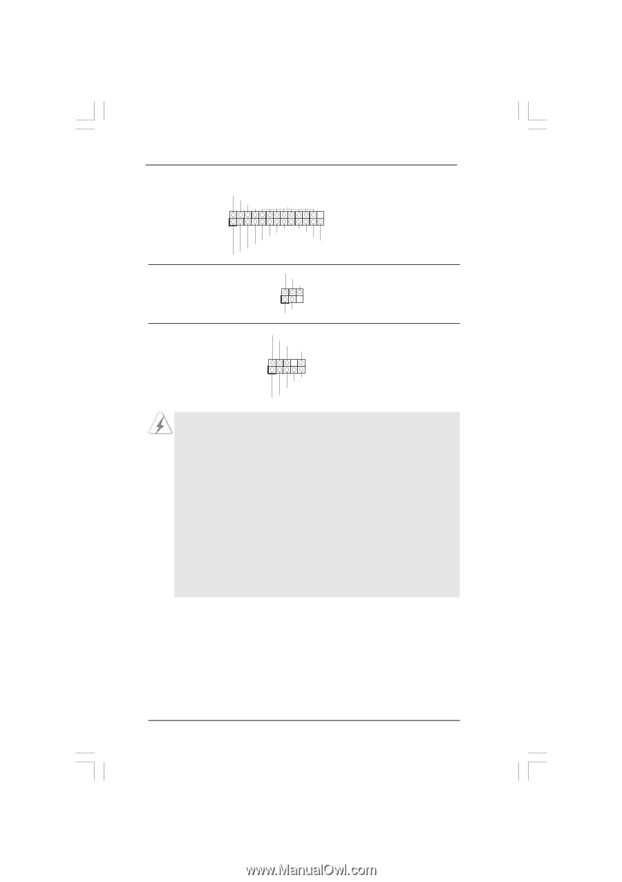
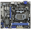
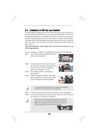
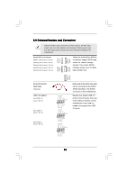
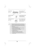
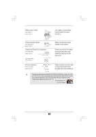
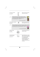
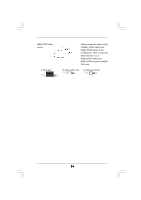
Print Port Header (25-pin LPT1) (see p.11 No. 24) AFD# ERROR# PINIT# SLIN# GND 1 SPD7 SPD6 ACK# SPD5 BUSY SPD4 PE SPD3 SLCT SPD2 SPD1 SPD0 STB# Infrared Module Header (5-pin IR1) (see p.11 No. 23) IRTX +5VSB DUMMY 1 GND IRRX Front Panel Audio Header (9-pin HD_AUDIO1) (see p.11 No. 26) GND PRESENCE# MIC_RET OUT_RET 1 OUT2_L J_SENSE OUT2_R MIC2_R MIC2_L This is an interface for print port cable that allows convenient connection of printer devices. This header supports an optional wireless transmitting and receiving infrared module. This is an interface for front panel audio cable that allows convenient connection and control of audio devices. 1. High Definition Audio supports Jack Sensing, but the panel wire on the chassis must support HDA to function correctly. Please follow the instruction in our manual and chassis manual to install your system. 2. If you use AC'97 audio panel, please install it to the front panel audio header as below: A. Connect Mic_IN (MIC) to MIC2_L. B. Connect Audio_R (RIN) to OUT2_R and Audio_L (LIN) to OUT2_L. C. Connect Ground (GND) to Ground (GND). D. MIC_RET and OUT_RET are for HD audio panel only. You don't need to connect them for AC'97 audio panel. E. To activate the front mic. For Windows® XP / XP 64-bit OS: Select "Mixer". Select "Recorder". Then click "FrontMic". For Windows® 7 / 7 64-bit / VistaTM / VistaTM 64-bit OS: Go to the "FrontMic" Tab in the Realtek Control panel. Adjust "Recording Volume". 21
-
 1
1 -
2
-
3
-
4
-
5
-
6
-
7
-
8
-
9
-
10
-
11
-
12
-
13
-
14
-
15
-
 16
16 -
 17
17 -
 18
18 -
 19
19 -
 20
20 -
 21
21 -
 22
22 -
 23
23 -
 24
24 -
 25
25 -
 26
26 -
27
-
28
-
29
-
30
-
31
-
32
-
33
-
34
-
35
-
36
-
37
-
38
-
39
-
40
-
41
-
42
-
43
-
44
-
45
-
46
-
47
-
48
-
49
-
50
-
51
-
52
-
53
 |
 |