ASRock H55M/USB3 R2.0 User Manual - Page 22
Chassis and Power Fan Connectors
 |
View all ASRock H55M/USB3 R2.0 manuals
Add to My Manuals
Save this manual to your list of manuals |
Page 22 highlights
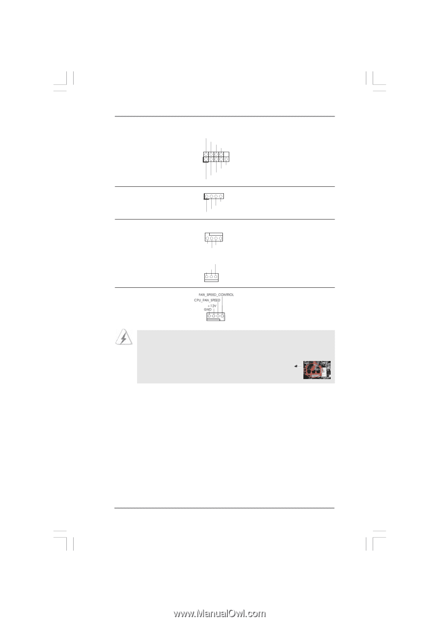
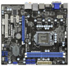
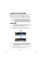
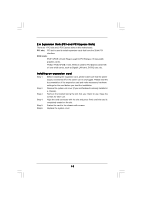
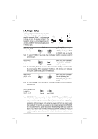
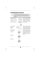
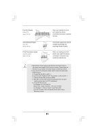
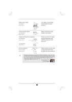
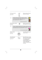
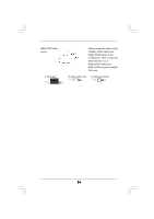
System Panel Header (9-pin PANEL1) (see p.11 No. 17) PLED+ PLEDPWRBTN# GND 1 DUMMY RESET# GND HDLEDHDLED+ Chassis Speaker Header (4-pin SPEAKER 1) (see p.11 No. 21) 1 SPEAKER DUMMY DUMMY +5V Chassis and Power Fan Connectors (4-pin CHA_FAN1) (see p.11 No. 22) FAN_SPEED_CONTROL GND +12V CHA_FAN_SPEED (3-pin PWR_FAN1) (see p.11 No. 4) PWR_FAN_SPEED +12V GND This header accommodates several system front panel functions. Please connect the chassis speaker to this header. Please connect the fan cables to the fan connectors and match the black wire to the ground pin. CPU Fan Connector (4-pin CPU_FAN1) (see p.11 No. 3) Please connect a CPU fan cable to this connector and match the black wire to the ground pin. 1 2 3 4 Though this motherboard provides 4-Pin CPU fan (Quiet Fan) support, the 3-Pin CPU fan still can work successfully even without the fan speed control function. If you plan to connect the 3-Pin CPU fan to the CPU fan connector on this motherboard, please connect it to Pin 1-3. Pin 1-3 Connected 3-Pin Fan Installation 22
-
 1
1 -
2
-
3
-
4
-
5
-
6
-
7
-
8
-
9
-
10
-
11
-
12
-
13
-
14
-
15
-
16
-
 17
17 -
 18
18 -
 19
19 -
 20
20 -
 21
21 -
 22
22 -
 23
23 -
 24
24 -
 25
25 -
 26
26 -
 27
27 -
28
-
29
-
30
-
31
-
32
-
33
-
34
-
35
-
36
-
37
-
38
-
39
-
40
-
41
-
42
-
43
-
44
-
45
-
46
-
47
-
48
-
49
-
50
-
51
-
52
-
53
 |
 |