ASRock J3160TM-ITX User Manual - Page 20
Signal, 3W Audio AMP Output
 |
View all ASRock J3160TM-ITX manuals
Add to My Manuals
Save this manual to your list of manuals |
Page 20 highlights
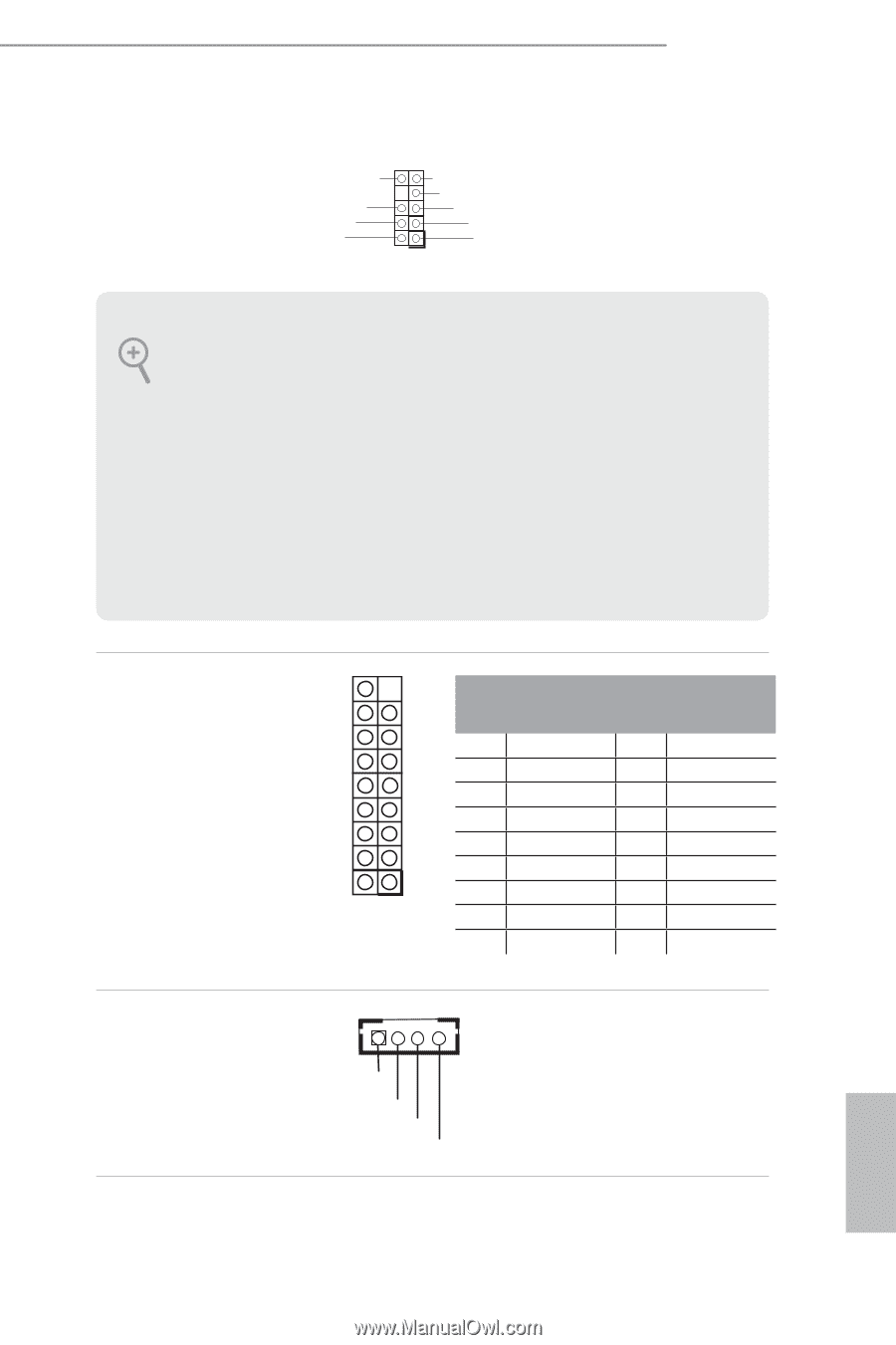
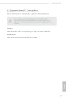
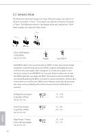
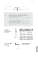
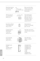
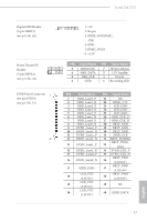
J3160TM-ITX Front Panel Audio Header GN D (9-pin HD_AUDIO1) (see p.5, No. 25) PRESENCE# MIC_RET OUT_RET OUT2_L J_SENSE This header is for connecting audio devices OUT2_R MIC2_R to the front audio panel. MIC2_L 1 1. High Definition Audio supports Jack Sensing, but the panel wire on the chassis must support HDA to function correctly. Please follow the instructions in our manual and chassis manual to install your system. 2. If you use an AC'97 audio panel, please install it to the front panel audio header by the steps below: A. Connect Mic_IN (MIC) to MIC2_L. B. Connect Audio_R (RIN) to OUT2_R and Audio_L (LIN) to OUT2_L. C. Connect Ground (GND) to Ground (GND). D. MIC_RET and OUT_RET are for the HD audio panel only. You don't need to connect them for the AC'97 audio panel. E. To activate the front mic, go to the "FrontMic" Tab in the Realtek Control panel and adjust "Recording Volume". Analog Surround Audio Header (17-pin HD_AUDIO2) (see p.5, No. 28) Signal Signal PIN PIN Name Name 18 SENSE 17 KEY 16 LFE 15 A_GND 14 A_GND 13 Center 12 Surr_Rear_R 11 A_GND 10 A_GND 9 Surr_Rear_L 8 Surr_Side_R 7 A_GND 2 1 6 A_GND 5 Surr_Side_L 4 Front_R 3 A_GND 2 A_GND 1 Front_L 3W Audio AMP Output Wafer Header (4-pin SPEAKER1) (see p.5, No. 27) 1 Front_LFront_L+ Front_R+ Front_R- Please connect the chassis speaker to this header. English 15
-
 1
1 -
2
-
3
-
4
-
5
-
6
-
7
-
8
-
9
-
10
-
11
-
12
-
13
-
14
-
 15
15 -
 16
16 -
 17
17 -
 18
18 -
 19
19 -
 20
20 -
 21
21 -
 22
22 -
 23
23 -
 24
24 -
 25
25 -
26
-
27
-
28
-
29
-
30
-
31
-
32
-
33
-
34
-
35
-
36
-
37
-
38
-
39
-
40
-
41
-
42
-
43
-
44
-
45
-
46
-
47
-
48
-
49
-
50
-
51
-
52
-
53
-
54
-
55
-
56
-
57
 |
 |