ASRock J3160TM-ITX User Manual - Page 23
Signal, Signal Name, Platform Module TPM system
 |
View all ASRock J3160TM-ITX manuals
Add to My Manuals
Save this manual to your list of manuals |
Page 23 highlights
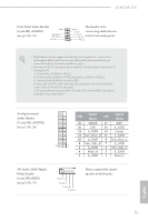
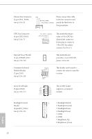
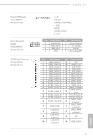
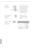
TPM Header (17-pin TPMS1) (see p.5, No. 19) F_CLKRUN# SERIRQ# S_PWRDWN# GND LAD1_L LAD2_L SMB_DATA_MAIN SMB_CLK_MAIN GND GND +3VSB LAD0_L +3V LAD3_L TPM_RST# LFRAME#_L CK_33M_TPM 1 This connector supports Trusted Platform Module (TPM) system, which can securely store keys, digital certificates, passwords, and data. A TPM system also helps enhance network security, protects digital identities, and ensures platform integrity. Monitor Switch Header (2-pin MONITOR_ SWITCH1) (see p.5, No. 5) 1 PWRDN GND This header can be used to connect a switch that turns on/ off the LVDS panel display's backlight. Digital Input / Output Pin Header 1 (10-pin JGPIO1) (see p.5, No. 23) Signal PIN PIN Signal Name Name JGPIOPWR (use JGPIO_ 6 GND 5 PWR1 to configure) 4 GPIO4 3 GPIO3 2 GPIO2 1 GPIO1 English 18
-
 1
1 -
2
-
3
-
4
-
5
-
6
-
7
-
8
-
9
-
10
-
11
-
12
-
13
-
14
-
15
-
16
-
17
-
 18
18 -
 19
19 -
 20
20 -
 21
21 -
 22
22 -
 23
23 -
 24
24 -
 25
25 -
 26
26 -
 27
27 -
 28
28 -
29
-
30
-
31
-
32
-
33
-
34
-
35
-
36
-
37
-
38
-
39
-
40
-
41
-
42
-
43
-
44
-
45
-
46
-
47
-
48
-
49
-
50
-
51
-
52
-
53
-
54
-
55
-
56
-
57
 |
 |
