ASRock J3455 Pro BTC User Manual - Page 20
Important: Make sure, on the graphics card are
 |
View all ASRock J3455 Pro BTC manuals
Add to My Manuals
Save this manual to your list of manuals |
Page 20 highlights
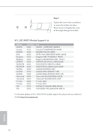
J3455 Pro BTC+ CPU Fan Connector (4-pin CPU_FAN1) (see p.5, No. 7) ATX Power Connectors (24-pin ATXPWR1) (see p.5, No. 8) (24-pin ATXPWR2) (see p.5, No. 6) ATX 12V Power Connector (8-pin ATX12V1) (see p.5, No. 30) PCIe Power Connectors (4-pin PCIE_PWR3) (see p.5, No. 15) (4-pin PCIE_PWR4) (see p.5, No. 17) (4-pin PCIE_PWR5) (see p.5, No. 18) (4-pin PCIE_PWR6) (see p.5, No. 20) (4-pin PCIE_PWR7) (see p.5, No. 21) (4-pin PCIE_PWR8) (see p.5, No. 23) 4 3 21 GND FAN_VOLTAGE CPU_FAN_SPEED FAN_SPEED_CONTROL This motherboard provides a 4-Pin CPU fan (Quiet Fan) connector. If you plan to connect a 3-Pin CPU fan, please connect it to Pin 1-3. 12 24 1 13 This motherboard provides two 24-pin ATX power connectors. To use a 20-pin ATX power supply, please plug it along Pin 1 and Pin 13. 8 5 This motherboard provides a 8-pin ATX 12V 4 1 power connector. To use a 4-pin ATX power supply, please plug it along Pin 1 and Pin 5. Please connect these connectors to the power supplies. Important: Make sure the 4-pin PCIe power connector and the external power connector on the graphics card are connected to the same PSU; otherwise, the motherboard and the graphics card may be damaged. English 15
-
 1
1 -
2
-
3
-
4
-
5
-
6
-
7
-
8
-
9
-
10
-
11
-
12
-
13
-
14
-
 15
15 -
 16
16 -
 17
17 -
 18
18 -
 19
19 -
 20
20 -
 21
21 -
 22
22 -
 23
23 -
 24
24 -
 25
25 -
26
-
27
-
28
-
29
-
30
-
31
-
32
-
33
-
34
-
35
-
36
-
37
-
38
-
39
-
40
-
41
-
42
-
43
-
44
-
45
-
46
-
47
-
48
-
49
-
50
-
51
-
52
 |
 |
