ASRock K7VT2 User Manual - Page 12
CD-ROM, DVD-ROM, TV - ata 133
 |
View all ASRock K7VT2 manuals
Add to My Manuals
Save this manual to your list of manuals |
Page 12 highlights
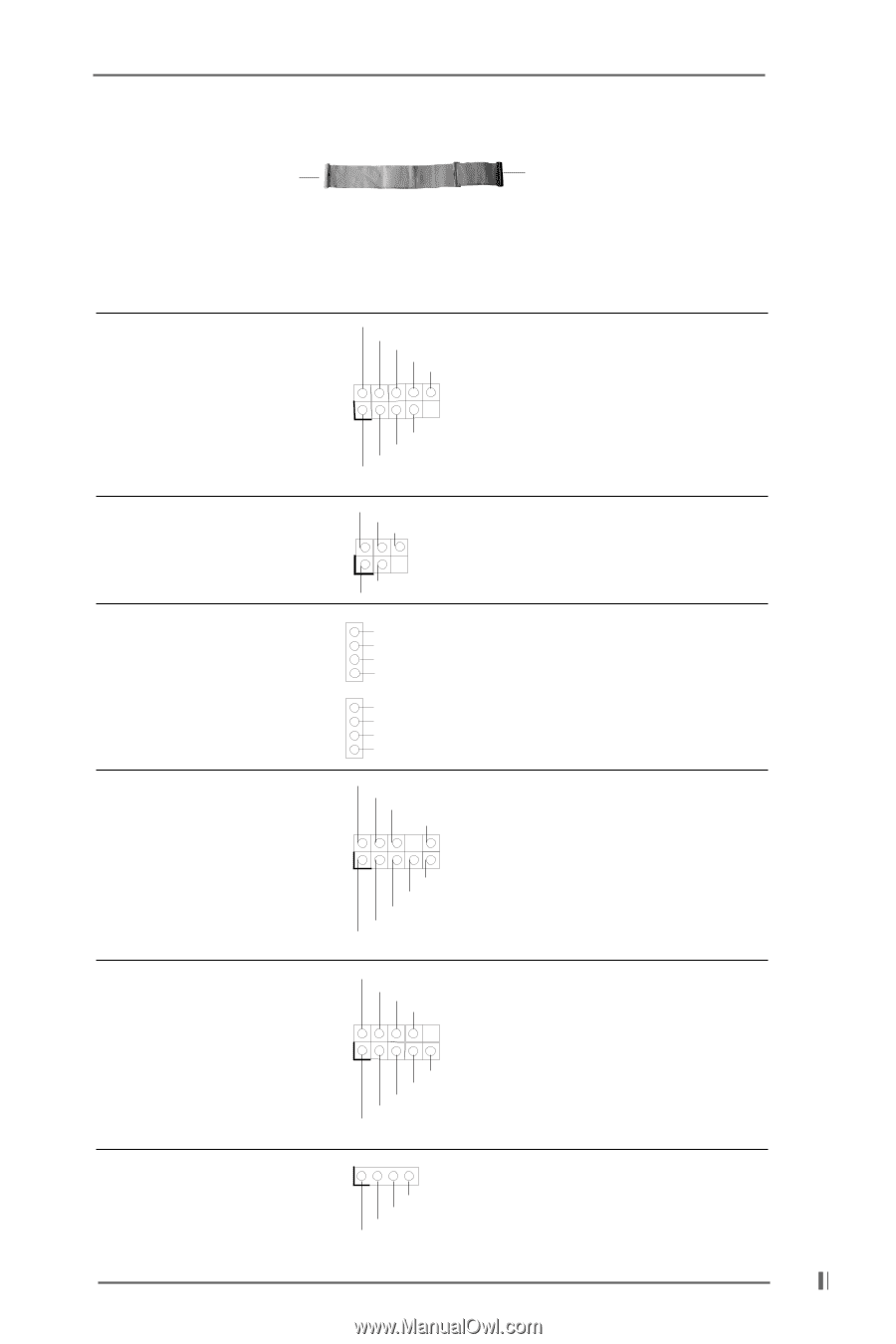
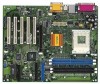
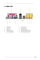
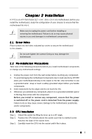
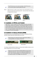
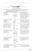
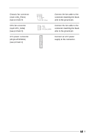
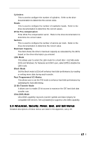
BLUE Connect to the motherboard BLACK Connect to the IDE devices 80-Pin ATA 100/133 cable Note: To optimize compatibility and performance, please connect your hard disk drive to the primary IDE connector (IDE1, blue) and CD-ROM to the secondary IDE connector (IDE2, black). USB header (9-pin USB45) (see p.6 item 13) USB_PWR P-5 P+5 GND DUMMY ASRock I/OTM already provided 4 default USB ports. If the 4 USB ports on the rear 1 panel are not sufficient, an GND P+4 P-4 USB_PWR USB header is available for 2 additional USB ports. Infrared module connector (5-pin IR1) (see p.6 item 14) Internal audio connectors (4-pin CD1, 4-pin AUX1) (CD1: see p.6 item 25) (AUX1: see p.6 item 24) IRTX +5V DUMMY 1 GND IRRX CD-R GND GND CD-L CD1 AUX-R GND GND AUX-L AUX1 Front panel audio connector (9-pin AUDIO1) (see p.6 item 20) GND +5VA BACKOUT-R BACKOUT-L 1 A U D - O U T- L DUMMY A U D - O U T- R MIC-POWER MIC This connector supports an optional wireless transmitting and receiving infrared module. These connectors allow you to receive stereo audio input from sound sources such as a CD-ROM, DVD-ROM, TV tuner card, or MPEG card. This is an interface for front panel audio cable that allows convenient connection and control of audio devices. System panel connector (9-pin PANEL1) (see p.6 item 12) PLED+ PLEDPWRBTN# GND 1 DUMMY RESET# GND HDLEDHDLED+ This connector accommodates several system front panel functions. External speaker connector (4-pin SPEAKER 1) (see p.6 item 15) 1 SPEAKER DUMMY DUMMY +5V This connector allows you to attach to an external speaker. 12
-
 1
1 -
2
-
3
-
4
-
5
-
6
-
 7
7 -
 8
8 -
 9
9 -
 10
10 -
 11
11 -
 12
12 -
 13
13 -
 14
14 -
 15
15 -
 16
16 -
 17
17 -
18
-
19
-
20
-
21
-
22
-
23
-
24
 |
 |