ASRock K7VT2 User Manual - Page 6
Motherboard Layout
 |
View all ASRock K7VT2 manuals
Add to My Manuals
Save this manual to your list of manuals |
Page 6 highlights
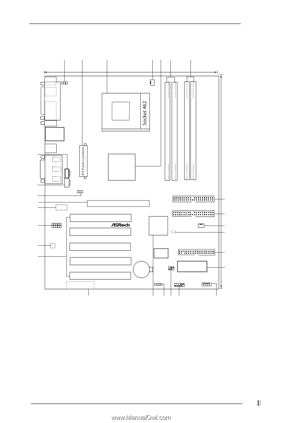
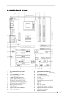
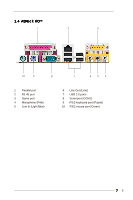
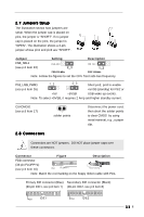
1.3 Motherboard Layout 26 1 2 34 5 6 24.4cm (9.6 in) PS/2 Mouse PS/2 Keyword 1 PS2_USB_PWR1 CPU_FAN1 COM1 PARALLEL PORT DDR DIMM1 (64/72 bit, 184-pin module) DDR DIMM2 (64/72 bit, 184-pin module) SDR DIMM1 (64 bit, 168-pin module) SDR DIMM2 (64 bit, 168-pin module) 30.5cm (12.0 in) LAN USB01 25 24 23 22 21 USB23 GGAAMMEE AAUUDDIIOO11 Line out LLIinnineein MMInicicin CD1 AUX1 FSB_SEL1 1 LAN PHY Audio1 20 VIA KT266A Chipset Accelerated Graphics Port PCI 1 PCI 2 01 23 01 23 7 IDE1 8 VIA IDE2 South 9 Bridge CLRCMOS1 CHA_FAN1 17 19 Audio CODEC 18 PCI 3 PCI 4 K7VT2 PCI 5 AMR1 Super 10 I/O FLOPPY1 CMOS IR1 2MB BIOS 11 Battery Speaker1 USB45 HDLED PWRBTN PANEL1 PLED RST 27 16 15 14 13 12 1 ATX power connector (ATXPWR1) 2 CPU socket 3 CPU fan connector (CPU_FAN1) 4 North Bridge controller 5 184-pin DDR DIMM slots (blue) 6 168-pin SDRAM DIMM slots (black) 7 Primary IDE connector (IDE1, blue) 8 Secondary IDE connector (IDE2, black) 9 Chassis fan connector (CHA_FAN1) 10 Floppy connector (FLOPPY1) 11 Flash EEPROM 12 System panel connector (PANEL1) 13 USB header (USB45) 14 Infrared module connector (IR1) 15 External speaker connector (SPEAKER 1) 16 South Bridge controller 17 Clear CMOS (CLRCMOS1) 18 PCI slots 19 Audio CODEC 20 Front panel audio connector (AUDIO1) 21 LAN PHY 22 AGP slot 23 FSB_SEL1 jumper 24 Internal audio connector: AUX1 (white) 25 Internal audio connector: CD1 (black) 26 PS2_USB_PWR1 jumper 27 AMR slot (Optional) 6
-
 1
1 -
 2
2 -
 3
3 -
 4
4 -
 5
5 -
 6
6 -
 7
7 -
 8
8 -
 9
9 -
 10
10 -
 11
11 -
 12
12 -
13
-
14
-
15
-
16
-
17
-
18
-
19
-
20
-
21
-
22
-
23
-
24
 |
 |