ASRock K8Upgrade-PCIE User Manual
ASRock K8Upgrade-PCIE Manual
 |
View all ASRock K8Upgrade-PCIE manuals
Add to My Manuals
Save this manual to your list of manuals |
ASRock K8Upgrade-PCIE manual content summary:
- ASRock K8Upgrade-PCIE | User Manual - Page 1
K8Upgrade-PCIE User Manual Version 1.0 Published May 2005 Copyright©2005 ASRock INC. All rights reserved. 1 - ASRock K8Upgrade-PCIE | User Manual - Page 2
any form or by any means, except duplication of documentation by the purchaser for backup purpose, without written consent of ASRock Inc. Products and corporate names appearing in this manual may or may not be registered trademarks or copyrights of their respective companies, and are used only for - ASRock K8Upgrade-PCIE | User Manual - Page 3
of CPU Fan and Heatsink 11 2.3 Installation of Memory Modules (DIMM 12 2.4 Expansion Slots (Future CPU Port, PCI and PCI Express Slots) ..... 13 2.5 Jumpers Setup 15 2.6 Onboard Headers and Connectors 16 2.7 Serial ATA (SATA) Hard Disks Installation 19 2.8 Making a SATA Driver Diskette For - ASRock K8Upgrade-PCIE | User Manual - Page 4
4 . Software Support 39 4.1 Install Operating System 39 4.2 Support CD Information 39 4.2.1 Running Support CD 39 4.2.2 Drivers Menu 39 4.2.3 Utilities Menu 39 4.2.4 Contact Information 39 APPENDIX: AMD's Cool 'n' QuietTM Technology ...... 40 4 - ASRock K8Upgrade-PCIE | User Manual - Page 5
x 20.3 cm) 1 x ASRock K8Upgrade-PCIE Quick Installation Guide 1 x ASRock K8Upgrade-PCIE Support CD 1 x Ultra ATA 66/100/133 IDE Ribbon Cable (80-conductor) 1 x 3.5-in Floppy Drive Ribbon Cable 1 x Serial ATA (SATA) Data Cable (Optional) 1 x Serial ATA (SATA) HDD Power Cable (Optional) 1 x ASRock 8CH - ASRock K8Upgrade-PCIE | User Manual - Page 6
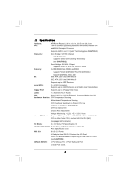
, PCI Specification 2.2 PCI EXPRESS Slots: 2 slots with PCIE x 1, 1 slot with PCIE x 16; PCIE Specification 1.0a USB 2.0: 8 USB 2.0 Ports: 4 Ready-to-Use USB 2.0 Ports on the I/O Panel Plus 2 On-Board Headers Supporting 4 Extra USB 2.0 Ports (see CAUTION 4) ASRock 8CH I/O: 1 PS/2 Mouse Port - ASRock K8Upgrade-PCIE | User Manual - Page 7
supports Untied Overclocking Technology. During overclocking, FSB enjoys better margin due to fixed PCI/PCIE buses. In other words, CPU FSB is untied during overclocking, but PCIE CPU fan on the motherboard functions properly and unplug the power cord, then plug it back again. To improve heat - ASRock K8Upgrade-PCIE | User Manual - Page 8
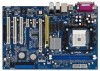
IDE2 K8Upgrade-PCIE PCI 1 ATA133 SiS 965L Chipset PCI 2 PCI 3 FLOPPY1 SATA1 USB2.0 USB45 1 USB67 1 SATA2 SPEAKER1 1 IR1 1 CHA_FAN1 PLED PWRBTN PANEL 1 1 HDLED RESET SATA 7 8 9 10 11 12 13 14 15 16 17 24 23 22 21 20 19 18 1 PS2_USB_PW1 Jumper 2 ATX 12V Power Connector (ATX12V1 - ASRock K8Upgrade-PCIE | User Manual - Page 9
1.4 ASRock 8CH I/O 1 13 12 11 2 3 6 4 7 5 8 10 9 1 Parallel Port 2 RJ-45 Port 3 Side Speaker (Gray) 4 Rear Speaker (Black) 5 Central / Bass (Orange) 6 Line In (Light Blue) *7 Front Speaker ( - ASRock K8Upgrade-PCIE | User Manual - Page 10
2. Installation K8Upgrade-PCIE is an ATX form factor (12.0-in x 8.0-in, 30.5 cm x 20.3 cm) settings. Before you install or remove any component, ensure that the power is switched off or the power cord is detached from the power supply. Failure to do so may cause severe damage to the motherboard - ASRock K8Upgrade-PCIE | User Manual - Page 11
that the CPU and the heatsink are securely fastened and in good contact with each other. Then connect the CPU fan to the CPU FAN connector (CPU_FAN1, see Page 8, No. 3). For proper installation, please kindly refer to the instruction manuals of the CPU fan and the heatsink. 11 - ASRock K8Upgrade-PCIE | User Manual - Page 12
with two 184-pin DDR (Double Data Rate) DIMM slots. Please make sure to disconnect power supply before adding or removing DIMMs or the system components. Step 1. Unlock a DIMM slot by pressing the retaining clips outward. Step 2. Align a DIMM on the slot such that the notch on the DIMM matches the - ASRock K8Upgrade-PCIE | User Manual - Page 13
required jumpers on K8Upgrade-PCIE motherboard. Please refer to the table below for the correct jumper settings. This yellow-colored Future CPU Port is not an AGP slot! Please do NOT insert any AGP card into it! CPU Type 754-Pin CPU (Default) 939-Pin CPU (Using add-on ASRock 939CPU Board) / 940 - ASRock K8Upgrade-PCIE | User Manual - Page 14
for PCI Express cards with x16 lane width graphics cards. PCIE2 / PCIE3 (PCIE x1 slot) is used for PCI Express cards, such as Gigabit LAN card, SATA II card, etc. Installing an expansion card Step 1. Before installing the expansion card, please make sure that the power supply is switched off or the - ASRock K8Upgrade-PCIE | User Manual - Page 15
jumpers JL1 and JR1 are short, both the front panel and the rear panel audio connectors can work. Clear CMOS Jumper (CLRCMOS2) (see p.8, No. 11) 2-pin to default setup, please turn off the computer and unplug the power cord from the power supply. After waiting for 15 seconds, use a jumper cap to - ASRock K8Upgrade-PCIE | User Manual - Page 16
please set the IDE device as "Master". Please refer to the instruction of your IDE device vendor for the details. Besides, to optimize compatibility p.8 No. 16) SATA1 SATA2 These two Serial ATA (SATA) connectors support SATA data cables for internal storage devices. The current SATA interface allows - ASRock K8Upgrade-PCIE | User Manual - Page 17
to the power connector of the power supply. USB 2.0 Header (9-pin USB67) (see p.8 No. 21) USB_PWR P-7 P+7 GND DUMMY 1 GND P+6 P-6 USB_PWR ASRock 8CH I/O accommodates 4 default USB 2.0 ports. If those USB 2.0 ports on the I/O panel are not sufficient, this USB 2.0 header is available to support - ASRock K8Upgrade-PCIE | User Manual - Page 18
wire to the ground pin. CPU_FAN_SPEED +12V GND Please connect the CPU fan cable to this connector and match the black wire to the ground pin. Please connect an ATX power supply to this connector. ATX 12V Power Connector (4-pin ATX12V1) (see p.8 No. 2) Please note that it is necessary to connect - ASRock K8Upgrade-PCIE | User Manual - Page 19
(SATA) Hard Disks Installation This motherboard supports Serial ATA (SATA) hard disks and RAID functions. This section will guide you to install the SATA hard disks. STEP 1: Install the SATA hard disks into the drive bays of your chassis. STEP 2: Connect the SATA power cable to the SATA hard disk - ASRock K8Upgrade-PCIE | User Manual - Page 20
a SATA driver before you start the OS installation. STEP 1: Insert the ASRock Support CD into your optical drive to boot your system. (Do NOT insert any Windows" in Windows environment. Please refer to the document in the Support CD, "Guide to SiS RAID Utility for Windows", which is located in the - ASRock K8Upgrade-PCIE | User Manual - Page 21
the motherboard stores the BIOS SETUP UTILITY. You may run the BIOS SETUP UTILITY when you start up the computer. Please press during the Power-On-Self-Test (POST) to enter the BIOS SETUP UTILITY, otherwise, POST will continue with its test routines. If you wish to enter the BIOS - ASRock K8Upgrade-PCIE | User Manual - Page 22
SETUP UTILITY Main Advanced H/W Monitor Boot Security Exit System Overview System Time System Date [17:00:09] [Tue 05/31/2005] BIOS Version : K8Upgrade-PCIE BIOS P1.0 Processor Type : AMD Athlon(tm) 64 Processor 3400+ Processor Speed : 2200 MHz Microcode Update : F7A/3A L1 Cache Size : 128KB L2 - ASRock K8Upgrade-PCIE | User Manual - Page 23
BIOS Version Processor Type Processor Speed Microcode Update L1 Cache Size L2 Cache Size : K8Upgrade-PCIE BIOS P1.0 : AMD Athlon(tm) 64 Processor 3400+ : 2200 MHz : 54 (C) Copyright 1985-2003, American Megatrends, Inc. If ASRock M2CPU Board is installed into the FUTURE_CPU_PORT on this motherboard - ASRock K8Upgrade-PCIE | User Manual - Page 24
3.3 Advanced Screen In this section, you may set the configurations for the following items: CPU Configuration, Chipset Configuration, ACPI Configuration, IDE Configuration, PCIPnP Configuration, Floppy Configuration, SuperIO Configuration, and USB Configuration. Main BIOS SETUP UTILITY Advanced - ASRock K8Upgrade-PCIE | User Manual - Page 25
If AUTO, multiplier and voltage will be left at the rated frequency/voltage. If Manual, multiplier and voltage will be set based on User Selection in Setup. +F1 value is [Auto]. Cnfiguration options: [Auto], [CPU, PCIE, Sync.] and [CPU, PCIE, Async.]. CPU Frequency (MHz) Use this option to adjust - ASRock K8Upgrade-PCIE | User Manual - Page 26
CPU Configuration Overclock Mode CPU Frequency (Mhz) PCIE Frequency (MHz) Boot Failure Guard Spread Spectrum American Megatrends, Inc. Processor Multiplier This item will show when "Multiplier/Voltage Change" is set to [Manual]; otherwise, it will be hidden. You may set the value from [x8] up to [x25 - ASRock K8Upgrade-PCIE | User Manual - Page 27
or disable the onboard LAN feature. Primary Graphics Adapter This item will switch the PCI Bus scanning order while searching for video card. It allows you to select the type of Primary VGA in case of multiple video controllers. The default value of this feature is [PCI]. Configuration options: [PCI - ASRock K8Upgrade-PCIE | User Manual - Page 28
BIOS SETUP UTILITY Advanced ACPI Settings Suspend To RAM Repost Video on STR Resume Restore on AC / Power Loss Ring-In Power On PCI Devices Power On PS / 2 Keyboard Power On RTC Alarm Power On [Auto] [No] [Power Off] [Disabled] [Disabled] [Disabled] [Disabled] Select auto-detect or disable - ASRock K8Upgrade-PCIE | User Manual - Page 29
On Use this item to enable or disable RTC (Real Time Clock) to power on the system. 3.3.4 IDE Configuration Advanced BIOS SETUP UTILITY IDE Configuration OnBoard IDE Controller OnBoard SATA Controller SATA Operation Mode Primary IDE Master Primary IDE - ASRock K8Upgrade-PCIE | User Manual - Page 30
. We will use the "Primary IDE Master" as the example in the following instruction, which can be applied to the configurations of "Primary IDE Slave", "Secondary IDE "Secondary IDE Slave" as well. However, if you plug PCIE-SATA2 card to this motherboard, the IDE Configuration screen will be as below - ASRock K8Upgrade-PCIE | User Manual - Page 31
Vendor Size LBA Mode Block Mode PIO Mode Async DMA Ultra DMA S.M.A.R.T. :Hard Disk :MAXTOR 6L080J4 :80.0 GB :Supported :16Sectors :4 :MultiWord DMA-2 :Ultra DMA-6 :Supported Type LBA/Large Mode Block (Multi-Sector Transfer) PIO Mode DMA Mode S.M.A.R.T. 32Bit Data Transfer [Auto] [Auto] [Auto - ASRock K8Upgrade-PCIE | User Manual - Page 32
the system to malfunction. PCI Latency Timer The default value is 32. It is recommended to keep the default value unless the installed PCI expansion cards' specifications require other settings. PCI IDE BusMaster Use this item to enable or disable the PCI IDE BusMaster feature. 32 - ASRock K8Upgrade-PCIE | User Manual - Page 33
3.3.6 Floppy Configuration In this section, you may configure the type of your floppy drive. BIOS SETUP UTILITY Advanced Floppy Configuration Floppy A Floppy B [1.44 MB 312"] [Disabled] Select the type of floppy drive connected to the system. +F1 F9 F10 ESC Select Screen Select Item Change - ASRock K8Upgrade-PCIE | User Manual - Page 34
Parallel Port Address Use this item to set the address for the onboard parallel port or disable it. Configuration options: [Disabled], [378], and [278]. Parallel Port Mode Use this item to set the operation mode of the parallel port. The default value is [ECP+EPP]. If this option is set to [ECP+EPP - ASRock K8Upgrade-PCIE | User Manual - Page 35
[Auto] so that the system will start to auto-detect; if there is no USB device connected, "Auto" option will disable the legacy USB support. 3.4 Hardware Health Event Monitoring Screen In this section, it allows you to monitor the status of the hardware on your system, including the parameters of - ASRock K8Upgrade-PCIE | User Manual - Page 36
3.5 Boot Screen In this section, it will display the available devices on your system for you to configure the boot settings and the boot priority. Main Advanced BIOS SETUP UTILITY H/W Monitor Boot Security Exit Boot Settings Boot Settings Configuration 1st Boot Device 2nd Boot Device 3rd - ASRock K8Upgrade-PCIE | User Manual - Page 37
3.6 Security Screen In this section, you may set or change the supervisor/user password for the system. For the user password, you may also clear it. BIOS SETUP UTILITY Main Advanced H/W Monitor Boot Security Exit Security Settings Supervisor Password : Not Installed User Password : Not - ASRock K8Upgrade-PCIE | User Manual - Page 38
3.7 Exit Screen Main BIOS SETUP UTILITY Advanced H/W Monitro Boot Security Exit Exit Options Save Changes and Exit Discard Changes and Exit Discard Changes Load Optimal Defaults Exit system setup after saving the changes. F10 key can be used for this operation. Select Screen Select Item - ASRock K8Upgrade-PCIE | User Manual - Page 39
click on the file "ASSETUP.EXE" from the BIN folder in the Support CD to display the menus. 4.2.2 Drivers Menu The Drivers Menu shows the available devices drivers including ASRock Express GbL PCI Express LAN card driver if the system detects the installed devices. Please install the necessary - ASRock K8Upgrade-PCIE | User Manual - Page 40
Support CD" first. If you are using Windows 2000/XP operating system, please follow the instruction below to enable AMD's Cool 'n' QuietTM technology: 1. From the Windows 2000/XP operating system, click the Start button. Select Settings, then Control Panel. 2. Switch From the Power Options Properties
-
 1
1 -
 2
2 -
 3
3 -
 4
4 -
 5
5 -
 6
6 -
 7
7 -
8
-
9
-
10
-
11
-
12
-
13
-
14
-
15
-
16
-
17
-
18
-
19
-
20
-
21
-
22
-
23
-
24
-
25
-
26
-
27
-
28
-
29
-
30
-
31
-
32
-
33
-
34
-
35
-
36
-
37
-
38
-
39
-
40
 |
 |

1
K8Upgrade-PCIE
User Manual
Version 1.0
Published May 2005
Copyright©2005 ASRock INC. All rights reserved.