ASRock K8Upgrade-PCIE User Manual - Page 18
ATX 12V Power Connector
 |
View all ASRock K8Upgrade-PCIE manuals
Add to My Manuals
Save this manual to your list of manuals |
Page 18 highlights
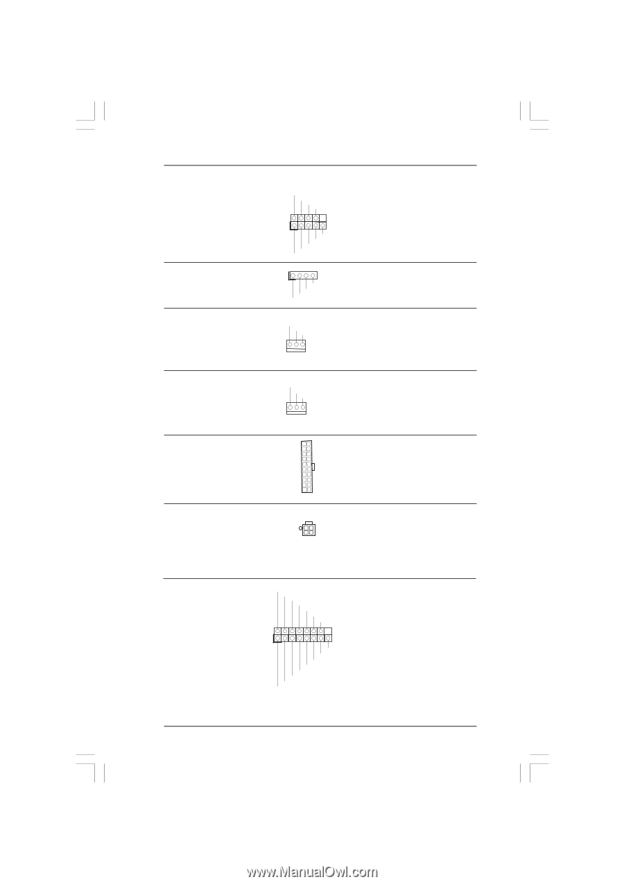
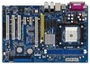
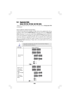
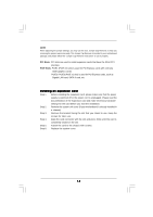
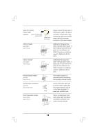
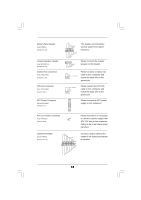
System Panel Header (9-pin PANEL1) (see p.8 No. 18) Chassis Speaker Header (4-pin SPEAKER 1) (see p.8 No. 17) Chassis Fan Connector (3-pin CHA_FAN1) (see p.8 No. 19) CPU Fan Connector (3-pin CPU_FAN1) (see p.8 No. 3) ATX Power Connector (20-pin ATXPWR1) (see p.8 No. 7) PLED+ PLEDPWRBTN# GND 1 DUMMY RESET# GND HDLEDHDLED+ 1 SPEAKER DUMMY DUMMY +5V GND +12V CHA_FAN_SPEED This header accommodates several system front panel functions. Please connect the chassis speaker to this header. Please connect a chassis fan cable to this connector and match the black wire to the ground pin. CPU_FAN_SPEED +12V GND Please connect the CPU fan cable to this connector and match the black wire to the ground pin. Please connect an ATX power supply to this connector. ATX 12V Power Connector (4-pin ATX12V1) (see p.8 No. 2) Please note that it is necessary to connect a power supply with ATX 12V plug to this connector. Failing to do so will cause power up failure. Game Port Header (15-pin GAME1) (see p.8 No. 24) +5V JBB1 JBX MIDI_OUT JBY JBB2 MIDI_IN 1 +5V JAB2 JAY GND GND JAX JAB1 +5V Connect a Game cable to this header if the Game port bracket is installed. 18
-
 1
1 -
2
-
3
-
4
-
5
-
6
-
7
-
8
-
9
-
10
-
11
-
12
-
 13
13 -
 14
14 -
 15
15 -
 16
16 -
 17
17 -
 18
18 -
 19
19 -
 20
20 -
 21
21 -
 22
22 -
 23
23 -
24
-
25
-
26
-
27
-
28
-
29
-
30
-
31
-
32
-
33
-
34
-
35
-
36
-
37
-
38
-
39
-
40
 |
 |