ASRock P4Twins-HDTV User Manual - Page 17
AV/S_2X3 cable to TV-OUT
 |
View all ASRock P4Twins-HDTV manuals
Add to My Manuals
Save this manual to your list of manuals |
Page 17 highlights
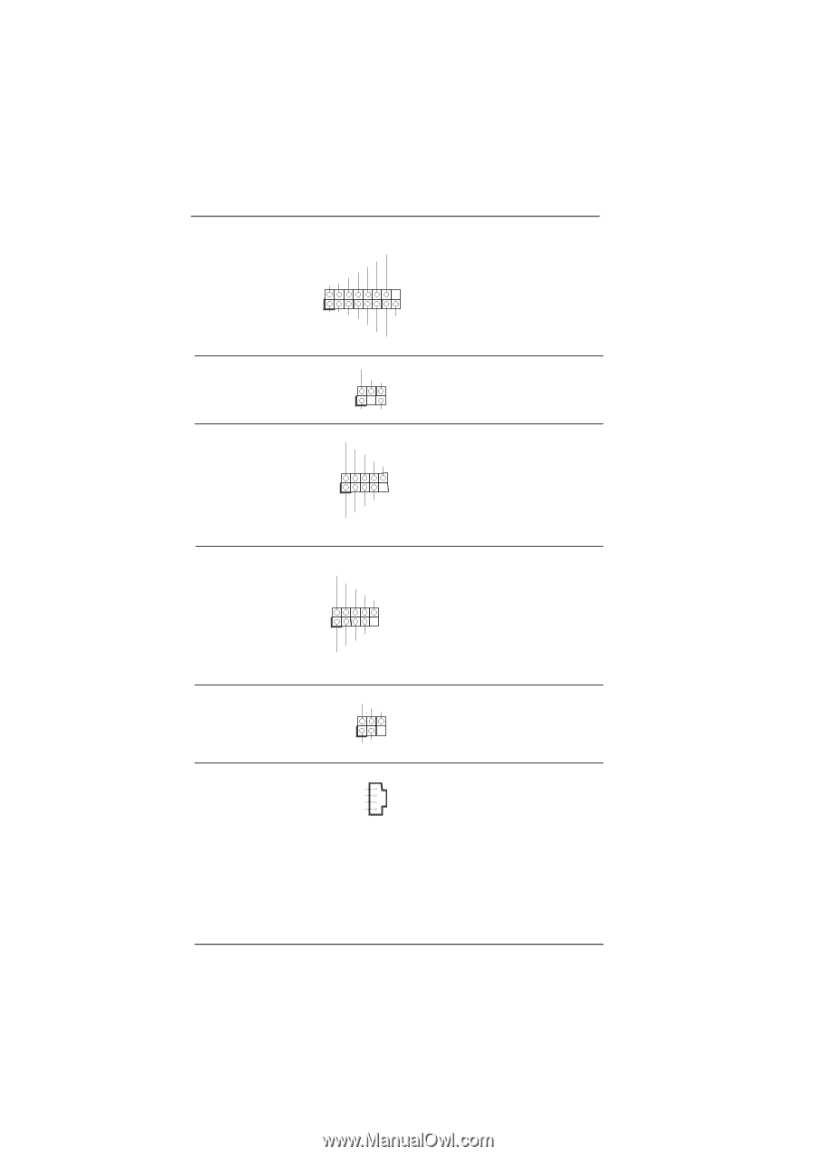
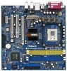
VGA Header (VGA1: see p.9 No. 32) TV-OUT Header (TV-OUT1: see p.9 No. 31) USB 2.0 Header (9-pin USB67) (see p.9 No. 21) RVSYNC DDCDATA GND GND GND GGND 1 R BGND GND DDCCLK IO+5V GND RHSYNC TV_COMP TV_C TV_Y 1 GND GND USB_PWR P-7 P+7 GND DUMMY 1 GND P+6 P-6 USB_PWR USB 2.0 Header (9-pin USB45) (see p.9 No. 20) USB_PWR P-5 P+5 GND DUMMY 1 GND P+4 P-4 USB_PWR Infrared Module Header (5-pin IR1) (see p.9 No. 25) IRTX +5VSB DUMMY 1 GND IRRX Internal Audio Connectors (4-pin CD1) (CD1: see p.9 No. 33) CD-R GND GND CD-L CD1 Please connect either end of VGA_2X8 cable to VGA header. Please connect either end of AV/S_2X3 cable to TV-OUT header. ASRock 8CH I/O accommodates 4 default USB 2.0 ports. If those USB 2.0 ports on the I/O panel are not sufficient, this USB 2.0 header is available to support 2 additional USB 2.0 ports. ASRock 8CH I/O accommodates 4 default USB 2.0 ports. If those USB 2.0 ports on the I/O panel are not sufficient, this USB 2.0 header is available to support 2 additional USB 2.0 ports. This header supports an optional wireless transmitting and receiving infrared module. This connector allows you to receive stereo audio input from sound sources such as a CD-ROM, DVD-ROM, TV tuner card, or MPEG card. 17
-
 1
1 -
2
-
3
-
4
-
5
-
6
-
7
-
8
-
9
-
10
-
11
-
 12
12 -
 13
13 -
 14
14 -
 15
15 -
 16
16 -
 17
17 -
 18
18 -
 19
19 -
 20
20 -
 21
21 -
 22
22 -
23
-
24
-
25
-
26
-
27
-
28
-
29
-
30
-
31
-
32
-
33
-
34
-
35
-
36
-
37
-
38
-
39
-
40
-
41
 |
 |