ASRock P4i45G User Manual - Page 17
pin CHA_FAN1
 |
View all ASRock P4i45G manuals
Add to My Manuals
Save this manual to your list of manuals |
Page 17 highlights
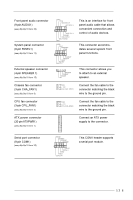
Front panel audio connector (9-pin AUDIO1) (see p.8/p.9/p.10 item 20) System panel connector (9-pin PANEL1) (see p.8/p.9/p.10 item 12) External speaker connector (4-pin SPEAKER 1) (see p.8/p.9/p.10 item 15) GND +5VA BACKOUT-R BACKOUT-L 1 A U D - O U T- L DUMMY A U D - O U T- R MIC-POWER MIC PLED+ PLEDPWRBTN# GND 1 DUMMY RESET# GND HDLEDHDLED+ 1 SPEAKER DUMMY DUMMY +5V This is an interface for front panel audio cable that allows convenient connection and control of audio devices. This connector accommodates several system front panel functions. This connector allows you to attach to an external speaker. Chassis fan connector (3-pin CHA_FAN1) (see p.8/p.9/p.10 item 9) GND +12V CHA_FAN_SPEED Connect the fan cable to the connector matching the black wire to the ground pin. CPU fan connector (3-pin CPU_FAN1) (see p.8/p.9/p.10 item 3) GND +12V CPU_FAN_SPEED Connect the fan cable to the connector matching the black wire to the ground pin. ATX power connector (20-pin ATXPWR1) (see p.8/p.9/p.10 item 1) Connect an ATX power supply to the connector. Serial port connector (9-pin COM1) (see p.8/p.9/p.10 item 25) RRXD1 DDTR#1 DDSR#1 CCTS#1 1 RRI#1 RRTS#1 GND TTXD1 DDCD#1 This COM1 header supports a serial port module. 17
-
 1
1 -
2
-
3
-
4
-
5
-
6
-
7
-
8
-
9
-
10
-
11
-
 12
12 -
 13
13 -
 14
14 -
 15
15 -
 16
16 -
 17
17 -
 18
18 -
 19
19 -
 20
20 -
 21
21 -
 22
22 -
23
-
24
-
25
-
26
-
27
-
28
-
29
 |
 |