ASRock Z390 Extreme4 User Manual
ASRock Z390 Extreme4 Manual
 |
View all ASRock Z390 Extreme4 manuals
Add to My Manuals
Save this manual to your list of manuals |
ASRock Z390 Extreme4 manual content summary:
- ASRock Z390 Extreme4 | User Manual - Page 1
- ASRock Z390 Extreme4 | User Manual - Page 2
change without notice, and should not be constructed as a commitment by ASRock. ASRock assumes no responsibility for any errors or omissions that may appear in CALIFORNIA, USA ONLY The Lithium battery adopted on this motherboard contains Perchlorate, a toxic substance controlled in Perchlorate Best - ASRock Z390 Extreme4 | User Manual - Page 3
if the goods fail to be of acceptable quality and the failure does not amount to a major failure. If you require assistance please call ASRock Tel : +886-2-28965588 ext.123 (Standard International call charges apply) The terms HDMI® and HDMI High-Definition Multimedia Interface, and the HDMI logo - ASRock Z390 Extreme4 | User Manual - Page 4
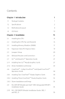
Two CrossFireXTM-Ready Graphics Cards 30 2.8.2 Installing Three CrossFireXTM-Ready Graphics Cards 32 2.8.3 Driver Installation and Setup 33 2.9 M.2 WiFi/BT Module and Intel® CNVi (Integrated WiFi/BT) Installation Guide 34 2.10 M.2_SSD (NGFF) Module Installation Guide (M2_1 and M2_2) 36 - ASRock Z390 Extreme4 | User Manual - Page 5
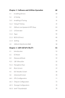
and Utilities Operation 40 3.1 Installing Drivers 40 3.2 A-Tuning 41 3.2.1 Installing A-Tuning 41 3.2.2 Using A-Tuning 41 3.3 ASRock Live Update & APP Shop 44 3.3.1 UI Overview 44 3.3.2 Apps 45 3.3.3 BIOS & Drivers 48 3.3.4 Setting 49 3.5 ASRock Polychrome RGB 50 Chapter - ASRock Z390 Extreme4 | User Manual - Page 6
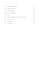
4.6.5 Super IO Configuration 80 4.6.6 ACPI Configuration 81 4.6.7 USB Configuration 83 4.6.8 Trusted Computing 84 4.7 Tools 85 4.8 Hardware Health Event Monitoring Screen 87 4.9 Security Screen 90 4.10 Boot Screen 91 4.11 Exit Screen 94 - ASRock Z390 Extreme4 | User Manual - Page 7
latest VGA cards and CPU support list on ASRock's website as well. ASRock website http://www.asrock.com. 1.1 Package Contents • ASRock Z390 Extreme4 Motherboard (ATX Form Factor) • ASRock Z390 Extreme4 Quick Installation Guide • ASRock Z390 Extreme4 Support CD • 1 x I/O Panel Shield • 4 x Serial ATA - ASRock Z390 Extreme4 | User Manual - Page 8
Intel® CoreTM Processors (Socket 1151) • Digi Power design • 12 Power Phase design • Supports Intel® Turbo Boost 2.0 Technology • Supports Intel® K-Series unlocked CPUs • Supports ASRock BCLK Full-range Overclocking • Intel® Z390 Memory • Dual Channel DDR4 Memory Technology • 4 x DDR4 DIMM Slots - ASRock Z390 Extreme4 | User Manual - Page 9
Z390 Extreme4 Graphics Audio • Intel® UHD Graphics Built-in Visuals and the VGA outputs can be supported only with processors which are GPU integrated. • Supports Intel® UHD Graphics Built-in Visuals : Intel® Quick Sync Video with AVC, MVC (S3D) and MPEG-2 Full HW Encode1, Intel® InTruTM 3D, Intel - ASRock Z390 Extreme4 | User Manual - Page 10
x Optical SPDIF Out Port • 1 x USB 3.1 Gen2 Type-A Port (10 Gb/s) (ReDriver) (Supports ESD Protection) • 1 x USB 3.1 Gen2 Type-C Port (10 Gb/s) (ReDriver) (Supports ESD Protection) • 4 x USB 3.1 Gen1 Ports (Intel® Z390) (Supports ESD Protection) • 1 x RJ-45 LAN Port with LED (ACT/LINK LED and SPEED - ASRock Z390 Extreme4 | User Manual - Page 11
Z390 Extreme4 * M2_1, SATA3_0 and SATA3_1 share lanes. If either one of them is in use, the others will be disabled. * M2_2, SATA3_4 and SATA3_5 share lanes. If either one of them is in use, the others will be disabled. • 1 x Ultra M.2 Socket (M2_1), supports M Key type 2230/2242/2260/2280 M.2 - ASRock Z390 Extreme4 | User Manual - Page 12
Gold Audio Connector) • 1 x Thunderbolt AIC Connector (5-pin) • 2 x USB 2.0 Headers (Support 4 USB 2.0 ports) (Intel® Z390) (Supports ESD Protection) • 2 x USB 3.1 Gen1 Headers (Support 4 USB 3.1 Gen1 ports) (ASMedia ASM1074 hub) (Supports ESD Protection) • 1 x Front Panel Type C USB 3.1 Gen1 Header - ASRock Z390 Extreme4 | User Manual - Page 13
Z390 Extreme4 * For detailed product information, please visit our website: http://www.asrock.com Please realize that there is a certain risk involved with overclocking, including adjusting the setting in the BIOS, applying Untied Overclocking Technology, or using third-party overclocking tools. - ASRock Z390 Extreme4 | User Manual - Page 14
1.3 Motherboard Layout 1 2 ATX12V1 ATX12V2 3 4 56 CPU_FAN1 CPU_FAN2/WP PS2 Keyboard /Mouse USB 3.1 FRONT Bottom: MIC IN Z390 EXTREME4 CHA_FAN1/WP Ultra M.2 PCIe Gen3 x4 LAN 1 9 USB3_7_8 M2_1 PCIE1 CT4 CT3 CT2 CT1 30 RoHS PCIE2 LAN M2_3 CMOS Battery 29 CLRMOS1 CT1 1 - ASRock Z390 Extreme4 | User Manual - Page 15
AIC Connector (TB1) 25 RGB LED Header (RGB_LED2) 26 RGB LED Header (RGB_LED1) 27 Addressable LED Header (ADDR_LED1) 28 Front Panel Audio Header (HD_AUDIO1) 29 Clear CMOS Jumper (CLRMOS1) 30 Chassis/Water Pump Fan Connector (CHA_FAN1/WP) Z390 Extreme4 English 9 - ASRock Z390 Extreme4 | User Manual - Page 16
1.4 I/O Panel 1 2 46 3 57 16 15 14 No. Description 1 PS/2 Mouse/Keyboard Port 2 D-Sub Port 3 LAN RJ-45 Port* 4 Central / Bass (Orange) 5 Rear Speaker (Black) 6 Line In (Light Blue) 7 Front Speaker (Lime)** 8 Microphone (Pink) 13 11 10 98 12 No. Description 9 Optical SPDIF Out Port 10 - ASRock Z390 Extreme4 | User Manual - Page 17
Z390 Extreme4 * There are two LEDs on each LAN port. Please refer to the table below for the LAN port LED indications. ACT/LINK LED SPEED LED - ASRock Z390 Extreme4 | User Manual - Page 18
to ensure that the motherboard fits into it. Pre-installation Precautions Take note of the following precautions before you install motherboard components or change any motherboard settings. • Make sure to unplug the power cord before installing or removing the motherboard components. Failure to do - ASRock Z390 Extreme4 | User Manual - Page 19
Z390 Extreme4 2.1 Installing the CPU 1. Before you insert the 1151-Pin CPU into the socket, please check if the PnP cap is on the CPU into the socket if above situation is found. Otherwise, the CPU will be seriously damaged. 2. Unplug all power cables before installing the CPU. 1 A B 2 13 English - ASRock Z390 Extreme4 | User Manual - Page 20
4 5 14 3 English - ASRock Z390 Extreme4 | User Manual - Page 21
Z390 Extreme4 Please save and replace the cover if the processor is removed. The cover must be placed if you wish to return the motherboard for after service. 15 English - ASRock Z390 Extreme4 | User Manual - Page 22
2.2 Installing the CPU Fan and Heatsink 1 2 CPU_FAN English 16 - ASRock Z390 Extreme4 | User Manual - Page 23
Z390 Extreme4 2.3 Installing Memory Modules (DIMM) This motherboard provides four 288-pin DDR4 (Double Data Rate 4) DIMM slots, and supports Dual Channel Memory Technology. 1. For dual channel configuration, you always need to install identical (the same brand, speed, size and chip-type) DDR4 - ASRock Z390 Extreme4 | User Manual - Page 24
1 2 3 18 English - ASRock Z390 Extreme4 | User Manual - Page 25
Z390 Extreme4 2.4 Expansion Slots (PCI Express Slots) There are 6 PCI Express slots on the motherboard. Before installing an expansion card, please make sure that the power supply is switched off or the power cord is unplugged. Please read the documentation of the - ASRock Z390 Extreme4 | User Manual - Page 26
no jumper cap is placed on the pins, the jumper is "Open". Clear CMOS Jumper (CLRCMOS1) (see p.8, No. 29) 2-pin Jumper Short: Clear CMOS Open: Default CLRCMOS1 allows you to clear the data in CMOS. The data in CMOS includes system setup information such as system password, date, time, and system - ASRock Z390 Extreme4 | User Manual - Page 27
Z390 Extreme4 2.6 Onboard Headers and Connectors Onboard headers and connectors are NOT jumpers. Do NOT place jumper caps over these headers and connectors. Placing jumper caps over the headers and connectors will cause permanent damage to the motherboard. System Panel Header (9-pin PANEL1) (see - ASRock Z390 Extreme4 | User Manual - Page 28
These eight SATA3 connectors support SATA data cables for Z390 SATA ports (SATA3_0) for your SSDs. USB 2.0 Headers (9-pin USB_1_2) (see p.8, No. 20) (9-pin USB_3_4) (see p.8, No. 19) USB_PWR PP+ GND DUMMY 1 GND P+ PUSB_PWR There are two headers on this motherboard. Each USB 2.0 header can support - ASRock Z390 Extreme4 | User Manual - Page 29
Z390 Extreme4 USB 3.1 Gen1 Headers (19- two headers on this motherboard. Each USB 3.1 Gen1 header can support two ports. Front supports Jack Sensing, but the panel wire on the chassis must support HDA to function correctly. Please follow the instructions in our manual and chassis manual to install - ASRock Z390 Extreme4 | User Manual - Page 30
CPU_FAN_SPEED (4-pin CPU_FAN2/WP) (see p.8, No. 4) FAN_VOLTAGE GND This motherboard 4 provides a 4-Pin water 3 2 cooling CPU fan 1 connector. Connector (24-pin ATXPWR1) (see p.8, No. 7) 12 24 1 13 This motherboard provides a 24-pin ATX power connector. To use a 20-pin ATX power supply, please - ASRock Z390 Extreme4 | User Manual - Page 31
Z390 Extreme4 ATX 12V Power B LAD0 +3V LAD3 PCIRST # FRAM E PCICLK 8 5 4 1 This motherboard provides an 8-pin ATX 12V power connector. To use a 4-pin ATX power install the Thunderbolt™ AIC card to PCIE6 (default slot). This COM1 header supports a serial port module. This connector supports - ASRock Z390 Extreme4 | User Manual - Page 32
cable which allows users to choose from various LED lighting effects. Caution: Never install the Addressable LED cable in the wrong orientation; otherwise, the cable may be damaged. *Please refer to page 51 for further instructions on this header. Please connect the OC switch and OC LED indicator on - ASRock Z390 Extreme4 | User Manual - Page 33
Z390 Extreme4 2.7 SLITM and Quad SLITM Operation Guide This motherboard supports NVIDIA® SLITM and Quad SLITM (Scalable Link Interface) technology that allows you to install Make sure that your graphics card driver supports NVIDIA® SLITM technology. Download the drivers from the NVIDIA® website: www - ASRock Z390 Extreme4 | User Manual - Page 34
SLI_HB_ Bridge_2S Card to the goldfingers on each graphics card. Make sure the ASRock SLI_ HB_Bridge_2S Card is firmly in place. SLI_HB_Bridge_2S Card ASRock SLI_HB_Bridge_2S Card Step 4 Connect a VGA cable or a DVI cable to the monitor connector or the DVI connector of the graphics card that is - ASRock Z390 Extreme4 | User Manual - Page 35
Z390 Extreme4 2.7.2 Driver Installation and Setup Install the graphics card drivers to your system. After that, you can enable the Multi-Graphics Processing Unit (GPU) in the NVIDIA® nView system tray utility. Please follow the below - ASRock Z390 Extreme4 | User Manual - Page 36
Quad CrossFireXTM Operation Guide This motherboard supports CrossFireXTM, 3-way CrossFireXTM and Quad CrossFireXTM that allows you to install up to CrossFireXTM. Please refer to AMD graphics card manuals for detailed installation guide. 2.8.1 Installing Two CrossFireXTM-Ready Graphics Cards Step 1 - ASRock Z390 Extreme4 | User Manual - Page 37
Z390 Extreme4 Step 3 Connect a VGA cable or a DVI cable to the monitor connector or the DVI connector of the graphics card that is inserted to PCIE2 slot. 31 English - ASRock Z390 Extreme4 | User Manual - Page 38
2.8.2 Installing Three CrossFireXTM-Ready Graphics Cards Step 1 Insert one graphics card PCIE6 slots. (The CrossFire Bridge is provided with the graphics card you purchase, not bundled with this motherboard. Please refer to your graphics card vendor for details.) Step 3 Connect a VGA cable or a DVI - ASRock Z390 Extreme4 | User Manual - Page 39
Z390 Extreme4 2.8.3 Driver Installation and Setup Step 1 Power on your computer and boot into OS. Step 2 Remove the AMD drivers if you have any VGA drivers installed in your system. The Catalyst Uninstaller is an optional download. We recommend using this utility to uninstall any previously - ASRock Z390 Extreme4 | User Manual - Page 40
Module and Intel® CNVi (Integrated WiFi/BT) Installation Guide The M.2, also known as the Next Generation Form Factor (NGFF), is a small size and versatile card edge connector that aims to replace mPCIe and mSATA. The M.2 Socket (Key E) supports type 2230 WiFi/BT module and Intel® CNVi (Integrated - ASRock Z390 Extreme4 | User Manual - Page 41
A A 20o A Z390 Extreme4 Step 3 Gently insert the WiFi/BT module or Intel® CNVi (Integrated WiFi/ BT) into the M.2 slot. Please be aware that the module only fits in one orientation. Step 4 Tighten the screw with a screwdriver to secure the module - ASRock Z390 Extreme4 | User Manual - Page 42
2.10 M.2_SSD (NGFF) Module Installation Guide (M2_1 and M2_2) The M.2, also known as the Next Generation Form Factor (NGFF), is a small size and versatile card edge connector that aims to replace mPCIe and mSATA. The Ultra M.2 Sockets (M2_1 and M2_2) support SATA3 6.0 Gb/s module and M.2 PCI Express - ASRock Z390 Extreme4 | User Manual - Page 43
1 2 1 Z390 Extreme4 Step 3 Before installing a M.2 (NGFF) SSD module, please loosen the screws to remove the M.2 heatsink. E D C B A Step4 Align and gently insert the M.2 (NGFF) SSD module into the M.2 slot. Please be - ASRock Z390 Extreme4 | User Manual - Page 44
M.2_SSD (NGFF) Module Support List Vendor ADATA ADATA ADATA ADATA ADATA ADATA ADATA ADATA ADATA ADATA Apacer Corsair Crucial Crucial Intel Intel Intel Kingston Kingston Kingston OCZ PATRIOT Plextor - ASRock Z390 Extreme4 | User Manual - Page 45
Z390 Extreme4 TEAM TEAM Transcend Transcend Transcend V-Color V-Color V-Color V-Color WD WD WD WD PCIe3 x4 WDS256G1X0C-00ENX0 (NVME) WDS512G1X0C-00ENX0 (NVME) For the latest updates of M.2_SSD (NFGG) module support list, please visit our website for details: http://www.asrock.com English 39 - ASRock Z390 Extreme4 | User Manual - Page 46
Chapter 3 Software and Utilities Operation 3.1 Installing Drivers The Support CD that comes with the motherboard contains necessary drivers and useful utilities that enhance the motherboard's features. Running The Support CD To begin using the support CD, insert the CD into your CD-ROM drive. The CD - ASRock Z390 Extreme4 | User Manual - Page 47
Z390 Extreme4 3.2 A-Tuning A-Tuning is ASRock's multi purpose software suite with a new interface, more new features and improved utilities. 3.2.1 Installing A-Tuning A-Tuning can be downloaded from ASRock Live Update & APP Shop. After the installation, you will find the icon "A-Tuning" on your - ASRock Z390 Extreme4 | User Manual - Page 48
OC Tweaker Configurations for overclocking the system. System Info View information about the system. *The System Browser tab may not appear for certain models. 42 English - ASRock Z390 Extreme4 | User Manual - Page 49
Z390 Extreme4 FAN-Tastic Tuning Configure up to five different fan speeds using the graph. The fans will automatically shift to the next speed level when the assigned temperature is met. Settings Configure ASRock A-Tuning. Click to select "Auto run at Windows Startup" if you want A-Tuning to be - ASRock Z390 Extreme4 | User Manual - Page 50
store for purchasing and downloading software applications for your ASRock computer. You can quickly and easily install various apps and support utilities.With ASRock Live Update & APP Shop, you can optimize your system and keep your motherboard up to date simply with a few clicks. Double-click - ASRock Z390 Extreme4 | User Manual - Page 51
Z390 Extreme4 3.3.2 Apps When the "Apps" tab is selected, you will see all the available apps on screen for you to download. Installing an App Step 1 Find the app you want to install the price or "Free" if the app is free of charge. - The green "Installed" icon means the app is installed on your - ASRock Z390 Extreme4 | User Manual - Page 52
Step 3 If you want to install the app, click on the red icon to start downloading. Step 4 When installation completes, you can find the green "Installed" icon appears on the upper right corner. English To uninstall it, simply click on the trash can icon . *The trash icon may not appear for - ASRock Z390 Extreme4 | User Manual - Page 53
Z390 Extreme4 Upgrading an App You can only upgrade the apps you have already installed. When there is an available new version for your app, you will find the mark of "New Version" appears below the installed app icon. Step 1 Click on the app icon to see more details. Step 2 Click on the yellow - ASRock Z390 Extreme4 | User Manual - Page 54
3.3.3 BIOS & Drivers Installing BIOS or Drivers When the "BIOS & Drivers" tab is selected, you will see a list of recommended or critical updates for the BIOS or drivers. Please update them all soon. Step 1 Please check the item information before update. Click on Step 2 to see more details. - ASRock Z390 Extreme4 | User Manual - Page 55
Z390 Extreme4 3.3.4 Setting In the "Setting" page, you can change the language, select the server location, and determine if you want to automatically run the ASRock Live Update & APP Shop on Windows startup. 49 English - ASRock Z390 Extreme4 | User Manual - Page 56
Connecting the LED Strip Connect your RGB LED strips to the RGB LED Headers (RGB_LED1, RGB_LED2) on the motherboard. Z390 EXTREME4 1 B R 12V G RGB_LED1 1 12V G R B RGB_LED2 1 12V G R B 1. Never install the RGB LED cable in the wrong orientation; otherwise, the cable may be damaged. 2. Before - ASRock Z390 Extreme4 | User Manual - Page 57
Connecting the Addressable RGB LED Strip Connect your Addressable RGB LED strip to the Addressable LED Header (ADDR_LED1) on the motherboard. ADDR_LED1 1 GND DO_ADDR VOUT Z390 EXTREME4 1 1. Never install the RGB LED cable in the wrong orientation; otherwise, the cable may be damaged. 2. Before - ASRock Z390 Extreme4 | User Manual - Page 58
RGB Utility. Download this utility from the ASRock Live Update & APP Shop and start coloring your PC style your way! Drag the tab to customize your preference. Toggle on/off the RGB LED switch Sync RGB LED effects for all LED regions of the motherboard Select a RGB LED light effect from the - ASRock Z390 Extreme4 | User Manual - Page 59
Z390 Extreme4 Chapter 4 UEFI SETUP UTILITY 4.1 Introduction This section explains how to use the UEFI SETUP UTILITY to configure your system. You may run the UEFI SETUP - ASRock Z390 Extreme4 | User Manual - Page 60
4.2 EZ Mode The EZ Mode screen appears when you enter the BIOS setup program by default. EZ mode is a dashboard which contains multiple readings of the system's current status. You can check the most crucial information of your system, such as CPU speed, DRAM frequency, SATA information, fan speed, - ASRock Z390 Extreme4 | User Manual - Page 61
Z390 Extreme4 4.3 Advanced Mode The Advanced Mode provides more options to configure the BIOS following selections: Main For setting system time/date information OC Tweaker For overclocking configurations Advanced For advanced system configurations Tool Useful tools H/W Monitor Displays - ASRock Z390 Extreme4 | User Manual - Page 62
4.3.2 Navigation Keys Use < > key or < > key to choose among the selections on the menu bar, and use < > key or < > key to move the cursor up or down to select items, then press to get into the sub screen. You can also use the mouse to click your required item. Please check the following - ASRock Z390 Extreme4 | User Manual - Page 63
Z390 Extreme4 4.4 Main Screen When you enter the UEFI SETUP UTILITY, the Main screen will appear and display the system overview. My Favorite Display your collection of BIOS items. Press F5 to add/remove your favorite items. 57 English - ASRock Z390 Extreme4 | User Manual - Page 64
appears only when your CPU supports this function. This option appears only when you adopt K-Series CPU. Load Optimized CPU OC Setting You can use this option to load optimized CPU overclocking setting. Please note that overclocking may cause damage to your CPU and motherboard. It should be done at - ASRock Z390 Extreme4 | User Manual - Page 65
Z390 Extreme4 CPU Configuration Performance mode Intel Performance Mode allows you to do real-time overclocking by pressing the OC button. The OC LED reminds you the Performance mode is ON. Please select the overclocking rule for Performance mode. [Disabled] Select this item to disable Intel - ASRock Z390 Extreme4 | User Manual - Page 66
Boost (TVB) feature. It is required to be disabled for supporting overclocking at frequencies higher than the default max turbo frequency. The default setting is [Disabled]. TVB Voltage Optimizations This service controls thermal based voltage optimizations for processors that implement the Intel - ASRock Z390 Extreme4 | User Manual - Page 67
Z390 Extreme4 Intel Speed Shift Technology Enable/Disable Intel Speed Shift Technology support. Enabling will expose the CPPC v2 interface to XMP settings to overclock the memory and perform beyond standard specifications. DRAM Frequency If [Auto] is selected, the motherboard will detect the memory - ASRock Z390 Extreme4 | User Manual - Page 68
Primary Timing CAS# Latency (tCL) The time between sending a column address to the memory and the beginning of the data in response. RAS# to CAS# Delay and Row Precharge (tRCDtRP) RAS# to CAS# Delay : The number of clock cycles required between the opening of a row of memory and accessing columns - ASRock Z390 Extreme4 | User Manual - Page 69
Z390 Extreme4 the same internal bank. Write to Read Delay (tWTR_S) The number of clocks between the last valid write operation and the next read command to - ASRock Z390 Extreme4 | User Manual - Page 70
tRDWR_dg Configure between module read to write delay. tRDWR_dr Configure between module read to write delay. tRDWR_dd Configure between module read to write delay. tWRRD_sg Configure between module write to read delay. tWRRD_dg Configure between module write to read delay. tWRRD_dr Configure - ASRock Z390 Extreme4 | User Manual - Page 71
Z390 Extreme4 RTL (CH A) Configure round trip latency for channel A. RTL (CH B) Configure round trip latency for channel B. IO-L (CH A) Configure IO on die termination resistors' WR for channel B2. ODT NOM (A1) Use this to change ODT (CH A1) Auto/Manual settings. The default is [Auto]. 65 English - ASRock Z390 Extreme4 | User Manual - Page 72
. The default is [Auto]. ODT NOM (B1) Use this to change ODT (CH B1) Auto/Manual settings. The default is [Auto]. ODT NOM (B2) Use this to change ODT (CH B2) Auto/Manual settings. The default is [Auto]. ODT PARK (A1) Configure the memory on die termination resistors' PARK for channel A1 - ASRock Z390 Extreme4 | User Manual - Page 73
Z390 Extreme4 Control Driving Adjust Control Driving for better signal. Default is 20. tCWL for Memory MRS MR2. MRS tCCD_L Configure the tCL for Memory MRS MR6. Advanced Setting ASRock Timing Optimization Configure the fast path through the MRC. Realtime Memory Timing Configure the realtime memory - ASRock Z390 Extreme4 | User Manual - Page 74
Command Tristate Configure the Command Tristate Support. Exit On Failure Configure the Exit On Failure for MRC training steps. Reset On Training Fail Reset system if the MRC training fails. MRC Fast - ASRock Z390 Extreme4 | User Manual - Page 75
Z390 Extreme4 VCCST Voltage Configure the voltage for the VCCST. VCCSA Voltage Configure the voltage for the VCCSA. VCCPLL Voltage Configure the voltage for the VCCPLL. Save - ASRock Z390 Extreme4 | User Manual - Page 76
UEFI setup utility. Full HD UEFI When [Auto] is selected, the resolution will be set to 1920 x 1080 if the monitor supports Full HD resolution. If the monitor does not support Full HD resolution, then the resolution will be set to 1024 x 768. When [Disable] is selected, the resolution will be set - ASRock Z390 Extreme4 | User Manual - Page 77
Z390 Extreme4 Intel Hyper Threading Technology Intel Hyper Threading Technology allows multiple threads to run on each core, so that the overall performance on threaded software is improved. Active Processor Cores Select the number of cores to enable in each processor package. CPU C States Support - ASRock Z390 Extreme4 | User Manual - Page 78
Enable C7 sleep state for lower power consumption. CPU C10 State Support Enable C10 sleep state for lower power consumption. Package C State Support Enable CPU, PCIe, Memory, Graphics C State Support for power saving. CFG Lock This item allows you to disable or enable the CFG Lock. CPU Thermal - ASRock Z390 Extreme4 | User Manual - Page 79
4.6.2 Chipset Configuration Z390 Extreme4 Primary Graphics Adapter Select a primary VGA. Above 4G Decoding Enable or disable 64bit capable Devices to be decoded in Above 4G Address Space (only if the system supports 64 bit PCI decoding). VT-d Intel® Virtualization Technology for Directed I/O helps - ASRock Z390 Extreme4 | User Manual - Page 80
the ASPM support for all PCH DMI devices. Share Memory Configure the size of memory that is allocated to the integrated graphics processor when the system boots up. IGPU Multi-Monitor Select disable to disable the integrated graphics when an external graphics card is installed. Select enable - ASRock Z390 Extreme4 | User Manual - Page 81
Z390 Extreme4 Front Panel Enable/disable front panel HD audio. Onboard HDMI HD Audio Enable audio for the onboard digital outputs. Deep Sleep Configure deep sleep mode - ASRock Z390 Extreme4 | User Manual - Page 82
Enable/disable the SATA controllers. SATA Mode Selection [AHCI] Supports new features that improve performance. [Intel RST Premium (RAID low power state during periods of inactivity to save power. It is only supported by AHCI mode. Hard Disk S.M.A.R.T. S.M.A.R.T stands for Self-Monitoring, Analysis - ASRock Z390 Extreme4 | User Manual - Page 83
Third Party SATA3 Mode [AHCI] Supports new features that improve performance. Z390 Extreme4 English 77 - ASRock Z390 Extreme4 | User Manual - Page 84
Enabled to allow booting from Bootable devices which are present behind Thunderbolt. Thunderbolt Usb Support Enabled to allow booting from Usb devices which are present behind Thunderbolt. Titan Ridge Workaround for OSUP Enable or disable Titan Ridge Workaround for OSUP. - ASRock Z390 Extreme4 | User Manual - Page 85
Windows 10 Thunderbolt support Specify Windows 10 Thunderbolt support level. Disabled: No OS native support. Enabled: OS Native support only. no RTD3. Z390 Extreme4 English 79 - ASRock Z390 Extreme4 | User Manual - Page 86
4.6.5 Super IO Configuration Serial Port Enable or disable the Serial port. Serial Port Address Select the address of the Serial port. PS2 Y-Cable Enable the PS2 Y-Cable or set this option to Auto. 80 English - ASRock Z390 Extreme4 | User Manual - Page 87
4.6.6 ACPI Configuration Z390 Extreme4 Suspend to RAM Select disable for ACPI suspend type S1. It is recommended to select auto for ACPI S3 power saving. PS/2 Keyboard S4/S5 Wakeup Support Allow the system to be waked up by a PS/2 Keyboard in S4/S5. PCIE Devices Power On Allow the system to be - ASRock Z390 Extreme4 | User Manual - Page 88
USB Mouse Power On Allow the system to be waked up by an USB mouse. 82 English - ASRock Z390 Extreme4 | User Manual - Page 89
4.6.7 USB Configuration Z390 Extreme4 Legacy USB Support Enable or disable Legacy OS Support for USB 2.0 devices. If you encounter USB compatibility issues it is recommended to disable legacy USB support. Select UEFI Setup Only to support USB devices under the UEFI setup and Windows/Linux - ASRock Z390 Extreme4 | User Manual - Page 90
4.6.8 Trusted Computing Security Device Support Enable or disable BIOS support for security device. 84 English - ASRock Z390 Extreme4 | User Manual - Page 91
4.7 Tools Z390 Extreme4 UEFI Tech Service Contact ASRock Tech Service if you are having trouble with your PC. Please setup network configuration before using UEFI Tech Service. Easy RAID Installer Easy RAID Installer helps you to copy the RAID driver from the support CD to your USB storage device. - ASRock Z390 Extreme4 | User Manual - Page 92
UEFI to duplicate the current working ROM image to the secondary flash ROM. This motherboard has two BIOS chips, an active BIOS (BIOS_A) and a backup BIOS (BIOS_B For safety issues, users are not able to update the backup BIOS manually. Users may refer to the BIOS LEDs (BIOS_A_LED or BIOS_B_LED) to - ASRock Z390 Extreme4 | User Manual - Page 93
Z390 Extreme4 4.8 Hardware Health Event Monitoring Screen This section allows you to monitor the status of the hardware on your system, including the parameters of the CPU temperature, motherboard temperature, fan speed and voltage. Fan Tuning Measure Fan Min Duty Cycle. Fan-Tastic Tuning Select a - ASRock Z390 Extreme4 | User Manual - Page 94
CPU_FAN2 / W_Pump Switch Select CPU or Water Pump mode. CPU_FAN2 Control Mode Select PWM mode or DC mode for CPU_FAN2. CPU_FAN2 Setting Select a fan mode for CPU_FAN2, or choose Customize to set 5 CPU temperatures and assign a respective fan speed for each temperature. CPU_FAN2 Temp Source Select a - ASRock Z390 Extreme4 | User Manual - Page 95
Z390 Extreme4 CHA_FAN2 Setting Select a fan mode for CHA_FAN2, or choose Customize to set 5 CPU temperatures and assign a respective fan Down. Over Temperature Protection When Over Temperature Protection is enabled, the system automatically shuts down when the motherboard is overheated. 89 English - ASRock Z390 Extreme4 | User Manual - Page 96
the supervisor/user password for the system. You may also clear the user password. Supervisor Password Set or change the password for remove the password. Secure Boot Use this item to enable or disable support for Secure Boot. Intel(R) Platform Trust Technology Enable/disable Intel PTT in ME - ASRock Z390 Extreme4 | User Manual - Page 97
boot from an USB storage device. The VBIOS must support UEFI GOP if you are using an external graphics card. Please notice that Ultra Fast mode will boot so fast that the only way to enter this UEFI Setup Utility is to Clear CMOS or run the Restart to UEFI utility in Windows - ASRock Z390 Extreme4 | User Manual - Page 98
If the computer fails to boot for a number of times the system automatically restores the default settings. CSM (Compatibility Support Module) CSM Enable to launch the Compatibility Support Module. Please do not disable unless you're running a WHCK test. Launch PXE OpROM Policy Select UEFI only to - ASRock Z390 Extreme4 | User Manual - Page 99
Z390 Extreme4 Launch Storage OpROM Policy Select UEFI only to run those that support UEFI option ROM only. Select Legacy only to run those that support legacy option ROM only. Select Do not launch to not execute both legacy and UEFI option ROM. Other PCI Device ROM Priority For PCI devices - ASRock Z390 Extreme4 | User Manual - Page 100
4.11 Exit Screen Save Changes and Exit When you select this option the following message, "Save configuration changes and exit setup?" will pop out. Select [OK] to save changes and exit the UEFI SETUP UTILITY. Discard Changes and Exit When you select this option the following message, "Discard - ASRock Z390 Extreme4 | User Manual - Page 101
or want to know more about ASRock, you're welcome to visit ASRock's website at http://www.asrock.com; or you may contact your dealer for further information. For technical questions, please submit a support request form at http://www.asrock.com/support/tsd.asp ASRock Incorporation 2F., No.37, Sec - ASRock Z390 Extreme4 | User Manual - Page 102
FCC Part 2 Section 2.1077(a) Responsible Party Name: ASRock Incorporation Address: 13848 Magnolia Ave, Chino, CA91710 Phone/Fax No: +1-909-590-8308/+1-909-590-1026 hereby declares that the product Product Name : Motherboard Model Number : Z390 Extreme4 Conforms to the following speci cations: FCC - ASRock Z390 Extreme4 | User Manual - Page 103
EU Declaration of Conformity For the following equipment: Motherboard (Product Name) Z390 Extreme4 / ASRock (Model Designation / Trade Name) ASRock Incorporation (Manufacturer Name) 2F., No.37, Sec. 2, Jhongyang S. Rd., Beitou District, Taipei City 112, Taiwan (R.O.C.) (Manufacturer Address)
-
 1
1 -
 2
2 -
 3
3 -
 4
4 -
 5
5 -
 6
6 -
 7
7 -
8
-
9
-
10
-
11
-
12
-
13
-
14
-
15
-
16
-
17
-
18
-
19
-
20
-
21
-
22
-
23
-
24
-
25
-
26
-
27
-
28
-
29
-
30
-
31
-
32
-
33
-
34
-
35
-
36
-
37
-
38
-
39
-
40
-
41
-
42
-
43
-
44
-
45
-
46
-
47
-
48
-
49
-
50
-
51
-
52
-
53
-
54
-
55
-
56
-
57
-
58
-
59
-
60
-
61
-
62
-
63
-
64
-
65
-
66
-
67
-
68
-
69
-
70
-
71
-
72
-
73
-
74
-
75
-
76
-
77
-
78
-
79
-
80
-
81
-
82
-
83
-
84
-
85
-
86
-
87
-
88
-
89
-
90
-
91
-
92
-
93
-
94
-
95
-
96
-
97
-
98
-
99
-
100
-
101
-
102
-
103
 |
 |