ASRock Z390 Extreme4 User Manual - Page 32
Never install the, be damaged.
 |
View all ASRock Z390 Extreme4 manuals
Add to My Manuals
Save this manual to your list of manuals |
Page 32 highlights
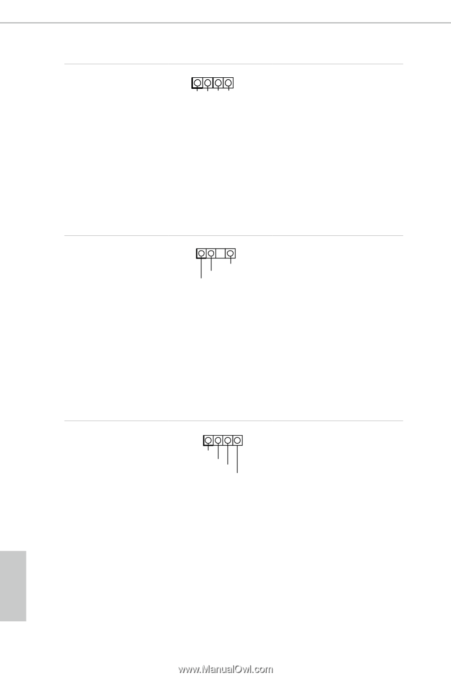
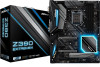
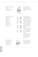
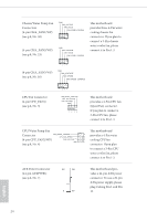
RGB LED Headers (4-pin RGB_LED1) (see p.8, No. 26) (4-pin RGB_LED2) (see p.8, No. 25) 1 12V G R B Addressable LED Header (3-pin ADDR_LED1) (see p.8, No. 27) 1 GND DO_ADDR VOUT Performance Mode / Easy OC Header (4-pin PM_OC) (see p.8, No. 15) 1 Button+ ButtonOCLED+ OCLED - RGB header is used to connect RGB LED extension cable which allows users to choose from various LED lighting effects. Caution: Never install the RGB LED cable in the wrong orientation; otherwise, the cable may be damaged. *Please refer to page 50 for further instructions on this header. This header is used to connect Addressable LED extension cable which allows users to choose from various LED lighting effects. Caution: Never install the Addressable LED cable in the wrong orientation; otherwise, the cable may be damaged. *Please refer to page 51 for further instructions on this header. Please connect the OC switch and OC LED indicator on the chassis to this header according to the pin assignments. Note the positive and negative pins before connecting the cables. English 26
-
 1
1 -
2
-
3
-
4
-
5
-
6
-
7
-
8
-
9
-
10
-
11
-
12
-
13
-
14
-
15
-
16
-
17
-
18
-
19
-
20
-
21
-
22
-
23
-
24
-
25
-
26
-
 27
27 -
 28
28 -
 29
29 -
 30
30 -
 31
31 -
 32
32 -
 33
33 -
 34
34 -
 35
35 -
 36
36 -
 37
37 -
38
-
39
-
40
-
41
-
42
-
43
-
44
-
45
-
46
-
47
-
48
-
49
-
50
-
51
-
52
-
53
-
54
-
55
-
56
-
57
-
58
-
59
-
60
-
61
-
62
-
63
-
64
-
65
-
66
-
67
-
68
-
69
-
70
-
71
-
72
-
73
-
74
-
75
-
76
-
77
-
78
-
79
-
80
-
81
-
82
-
83
-
84
-
85
-
86
-
87
-
88
-
89
-
90
-
91
-
92
-
93
-
94
-
95
-
96
-
97
-
98
-
99
-
100
-
101
-
102
-
103
 |
 |