ASRock Z690 Pro RS User Manual
ASRock Z690 Pro RS Manual
 |
View all ASRock Z690 Pro RS manuals
Add to My Manuals
Save this manual to your list of manuals |
ASRock Z690 Pro RS manual content summary:
- ASRock Z690 Pro RS | User Manual - Page 1
- ASRock Z690 Pro RS | User Manual - Page 2
documentation are furnished for informational use only and subject to change without notice, and should not be constructed as a commitment by ASRock. ASRock assumes no responsibility for any errors or omissions that may appear in this documentation. With respect to the contents of this documentation - ASRock Z690 Pro RS | User Manual - Page 3
not amount to a major failure. If you require assistance please call ASRock Tel : +886-2-28965588 ext.123 (Standard International call charges apply) other text or file. (e) Intel has no obligation to provide any support, technical assistance or updates for the Software. OWNERSHIP OF SOFTWARE AND - ASRock Z690 Pro RS | User Manual - Page 4
ES OF ANY KIND WHETHER UNDER THIS AGREEMENT OR OTHERWISE, EVEN IF INTEL HAS BEEN ADVISED OF THE POSSIBILITY OF SUCH DAMAGES. LICENSE TO USE COMMENTS AND SUGGESTIONS. This Agreement does NOT obligate Licensee to provide Intel with comments or suggestions regarding the Software. However, if Licensee - ASRock Z690 Pro RS | User Manual - Page 5
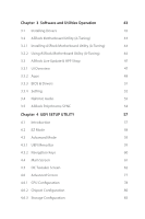
Setup 19 2.6 Onboard Headers and Connectors 20 2.7 Smart Button 26 2.8 Post Status Checker 27 2.9 CrossFireXTM and Quad CrossFireXTM Operation Guide 28 2.9.1 Installing Two CrossFireXTM-Ready Graphics Cards 28 2.9.2 Driver Installation and Setup 30 2.10 M.2 WiFi/BT PCIe WiFi Module - ASRock Z690 Pro RS | User Manual - Page 6
Update & APP Shop 47 3.3.1 UI Overview 47 3.3.2 Apps 48 3.3.3 BIOS & Drivers 51 3.3.4 Setting 52 3.4 Nahimic Audio 53 3.5 ASRock Polychrome SYNC 54 Chapter 4 UEFI SETUP UTILITY 57 4.1 Introduction 57 4.2 EZ Mode 58 4.3 Advanced Mode 59 4.3.1 UEFI Menu Bar 59 4.3.2 Navigation - ASRock Z690 Pro RS | User Manual - Page 7
4.6.4 Intel(R) Thunderbolt 84 4.6.5 Super IO Configuration 85 4.6.6 ACPI Configuration 86 4.6.7 USB Configuration 87 4.6.8 Trusted Computing 88 4.7 Tools 90 4.8 Hardware Health Event Monitoring Screen 92 4.9 Security Screen 96 4.10 Boot Screen 97 4.11 Exit Screen 100 - ASRock Z690 Pro RS | User Manual - Page 8
- ASRock Z690 Pro RS | User Manual - Page 9
find the latest VGA cards and CPU support list on ASRock's website as well. ASRock website http://www.asrock.com. 1.1 Package Contents • ASRock Z690 Pro RS Motherboard (ATX Form Factor) • ASRock Z690 Pro RS Quick Installation Guide • ASRock Z690 Pro RS Support CD • 2 x Serial ATA (SATA) Data Cables - ASRock Z690 Pro RS | User Manual - Page 10
• Intel® Z690 Memory • Dual Channel DDR4 Memory Technology • 4 x DDR4 DIMM Slots • Supports DDR4 non-ECC, un-buffered memory up to 4800+(OC)* * Supports DDR4 3200 natively. * Please refer to Memory Support List on ASRock's website for more information. (http://www.asrock.com/) • Supports ECC UDIMM - ASRock Z690 Pro RS | User Manual - Page 11
Z690 Pro RS • Dual graphics output: support HDMI and DisplayPort 1.4 ports by independent display controllers • Supports HDMI 2.1 TMDS Compatible with max. resolution up to 4K x 2K (4096x2160) @ 60Hz • Supports DisplayPort 1.4 with DSC (compressed) max. resolution up to 8K (8192x4320) @ 60Hz / 5K ( - ASRock Z690 Pro RS | User Manual - Page 12
PCIe Gen4x4 (64 Gb/s) mode** ** Supports Intel® OptaneTM Technology ** Supports Intel® Volume Management Device (VMD) ** Supports NVMe SSD as boot disks ** Supports ASRock U.2 Kit RAID • Supports RAID 0, RAID 1, RAID 5 and RAID 10 for SATA storage devices • Supports RAID 0, RAID 1 and RAID 5 for - ASRock Z690 Pro RS | User Manual - Page 13
Z690 Pro RS • 1 x 24 pin ATX Power Connector (Hi-Density Power Connector) • 1 x 8 pin 12V Power Connector (Hi-Density Power Connector) • 1 x 4 pin 12V Power Connector (Hi-Density Power Connector) • 1 x Front Panel Audio Connector • 1 x Thunderbolt AIC Connector (5-pin) (Supports ASRock Thunderbolt - ASRock Z690 Pro RS | User Manual - Page 14
Please realize that there is a certain risk involved with overclocking, including adjusting the setting in the BIOS, applying Untied Overclocking Technology, or using third-party overclocking tools. Overclocking may affect your system's stability, or even cause damage to the components and devices - ASRock Z690 Pro RS | User Manual - Page 15
1.3 Motherboard Layout Z690 Pro RS USB 2.0 T: USB_1 B: USB_2 PS2 Keyboard /Mouse 1 2 ATX12V1 ATX12V2 34 56 7 8 T B1 1 CHA_FAN2/WP CLRMOS1 1 1 USB_3_4 USB_5_6 1 M2_2 Intel Z690 SATA3_4 SATA3_5 SATA3_2 SATA3_3 SATA3_0 SATA3_1 M2_3 SATA3_7 BOOT CPU DRAM VGA SPI_TPM_J1 - ASRock Z690 Pro RS | User Manual - Page 16
No. Description 1 ATX 12V Power Connector (ATX12V1) 2 ATX 12V Power Connector (ATX12V2) 3 CPU Fan Connector (CPU_FAN1) 4 CPU/Water Pump Fan Connector (CPU_FAN2/WP) 5 2 x 288-pin DDR4 DIMM Slots (DDR4_A1, DDR4_B1) 6 2 x 288-pin DDR4 DIMM Slots (DDR4_A2, DDR4_B2) 7 Addressable LED Header (ADDR_LED3) 8 - ASRock Z690 Pro RS | User Manual - Page 17
1.4 I/O Panel 1 Z690 Pro RS 3 2 4 11 10 9 8 7 6 5 No. Description 1 USB 2.0 Ports (USB_1_2) 2 2.5G LAN RJ-45 Port (Dragon RTL8125BG)* 3 Line In (Light Blue)** 4 Front Speaker (Lime)** 5 Microphone (Pink)** No. Description 6 - ASRock Z690 Pro RS | User Manual - Page 18
1.5 Graphics Card Holder Installing the Graphics Card Holder Before installing the Graphics Card Holder , please make sure that your motherboard is properly installed into a PC case. Step 1 Secure the Graphics Card Holder to the chassis with 2 screws. Type A Type B *There are two types of screws - ASRock Z690 Pro RS | User Manual - Page 19
Z690 Pro RS Chapter 2 Installation This is an ATX form factor motherboard. Before you install the motherboard, study the configuration of your chassis to ensure that the motherboard - ASRock Z690 Pro RS | User Manual - Page 20
2.1 Installing the CPU 1. Before you insert the 1700-Pin CPU into the socket, please check if the PnP cap is on the socket, if the CPU surface is unclean, or if there are any bent pins in the socket. Do not force to insert the CPU into the socket if above situation is found. Otherwise, the CPU will - ASRock Z690 Pro RS | User Manual - Page 21
Z690 Pro RS 4 5 6 7 English 13 - ASRock Z690 Pro RS | User Manual - Page 22
Please save and replace the cover if the processor is removed. The cover must be placed if you wish to return the motherboard for after service. 14 English - ASRock Z690 Pro RS | User Manual - Page 23
2.2 Installing the CPU Fan and Heatsink Z690 Pro RS 1 2 CPU_FAN 15 English - ASRock Z690 Pro RS | User Manual - Page 24
2.3 Installing Memory Modules (DIMM) This motherboard provides four 288-pin DDR4 (Double Data Rate 4) DIMM slots, and supports Dual Channel Memory Technology. 1. For dual channel configuration, you always need to install identical (the same brand, speed, size and chip-type) DDR4 DIMM pairs. 2. - ASRock Z690 Pro RS | User Manual - Page 25
Z690 Pro RS 1 2 3 17 English - ASRock Z690 Pro RS | User Manual - Page 26
2.4 Expansion Slots (PCIe Slots) There are 5 PCIe slots on the motherboard. Before installing an expansion card, please make sure that the power supply is switched off or the power cord is unplugged. Please read the documentation of the expansion card and make necessary hardware settings for the - ASRock Z690 Pro RS | User Manual - Page 27
Z690 Pro RS 2.5 Jumpers Setup The illustration shows how jumpers are setup. When the jumper cap is placed on the pins, the jumper is "Short". If no jumper - ASRock Z690 Pro RS | User Manual - Page 28
2.6 Onboard Headers and Connectors Onboard headers and connectors are NOT jumpers. Do NOT place jumper caps over these headers and connectors. Placing jumper caps over the headers and connectors will cause permanent damage to the motherboard. System Panel Header (9-pin PANEL1) (see p.7, No. 20) - ASRock Z690 Pro RS | User Manual - Page 29
Z690 Pro RS Serial ATA3 Connectors Right Angle: (SATA3_0: see p.7, No. 17) (Upper) (SATA3_1: see p.7, No. 23) SATA3_0 SATA3_2 SATA3_4 SATA3_1 SATA3_3 SATA3_5 SATA3_7 SATA3_6 These eight SATA3 connectors support SATA data cables for internal storage devices with up to 6.0 Gb/s data transfer rate - ASRock Z690 Pro RS | User Manual - Page 30
for connecting audio devices to the front audio panel. 1. High Definition Audio supports Jack Sensing, but the panel wire on the chassis must support HDA to function correctly. Please follow the instructions in our manual and chassis manual to install your system. 2. If you use an AC'97 audio panel - ASRock Z690 Pro RS | User Manual - Page 31
Z690 Pro RS Chassis/Water Pump Fan Connectors (4-pin CHA_FAN1/WP) (see p.7, No. 32) (4-pin CHA_FAN2/WP) (see p.7, No. 26) (4-pin CHA_FAN3/WP) (see p.7, No. 12) GND FAN_VOLTAGE - ASRock Z690 Pro RS | User Manual - Page 32
ATX Power Connector (24-pin ATXPWR1) (see p.7, No. 10) ATX 12V Power Connector (8-pin ATX12V1) (see p.7, No. 1) ATX 12V Power Connector (4-pin ATX12V2) (see p.7, No. 2) 12 24 1 13 8 5 4 1 This motherboard provides a 24-pin ATX power connector. To use a 20-pin ATX power supply, please plug - ASRock Z690 Pro RS | User Manual - Page 33
Z690 Pro RS SPI TPM Header (13-pin SPI_TPM_J1 1 SPI_TPM_CS# GND RSMRST# SPI_MISO SPI_CS0 SPI_DQ2 This connector supports SPI Trusted Platform Module (TPM) system, which can may be damaged. *Please refer to page 54 for further instructions on this header. 1 GND DO_ADDR VOUT These headers are - ASRock Z690 Pro RS | User Manual - Page 34
an unpredictable failure may occur. To use the USB BIOS Flashback function, Please follow the steps below. 1. Download the latest BIOS file from ASRock's website : http://www.asrock.com. 2. Copy the BIOS file to your USB flash drive. Please make sure the file system of your USB flash drive must be - ASRock Z690 Pro RS | User Manual - Page 35
Z690 Pro RS 2.8 Post Status Checker Post Status Checker (PSC) diagnoses the computer when users power on the machine. It emits a red light to indicate whether the CPU, memory, VGA or storage is dysfunctional. The lights go off if the four mentioned above are functioning normally. 27 English - ASRock Z690 Pro RS | User Manual - Page 36
that are AMD certified. 2. Make sure that your graphics card driver supports AMD CrossFireXTM technology. Download the drivers from the AMD's website: www. CrossFireXTM. Please refer to AMD graphics card manuals for detailed installation guide. 2.9.1 Installing Two CrossFireXTM-Ready Graphics Cards - ASRock Z690 Pro RS | User Manual - Page 37
Z690 Pro RS Step 3 Connect a VGA/DVI/DP/HDMI cable from the monitor to the corresponding port on the graphics card installed to the PCIE2 slot. 29 English - ASRock Z690 Pro RS | User Manual - Page 38
2.9.2 Driver Installation and Setup Step 1 Power on your computer and boot into OS. Step 2 Remove the AMD drivers if you have any VGA drivers installed in your system. The Catalyst Uninstaller is an optional download. We recommend using this utility to uninstall any previously installed Catalyst - ASRock Z690 Pro RS | User Manual - Page 39
Z690 Pro RS 2.10 M.2 WiFi/BT PCIe WiFi Module and Intel® CNVi (Integrated WiFi/BT) Installation Guide The M.2, also known as the Next Generation Form Factor (NGFF), is a small size and versatile card edge connector that aims to replace mPCIe and mSATA. The M.2 Socket (Key E) supports type 2230 WiFi/ - ASRock Z690 Pro RS | User Manual - Page 40
A A 20o A Step 3 Gently insert the WiFi/BT module or Intel® CNVi (Integrated WiFi/ BT) into the M.2 slot. Please be aware that the module only fits in one orientation. Step 4 Tighten the screw with a screwdriver to secure the module into place. Please do not overtighten the screw as this might - ASRock Z690 Pro RS | User Manual - Page 41
Z690 Pro RS 2.11 M.2_SSD (NGFF) Module Installation Guide (M2_1) The M.2, also known as the Next Generation Form Factor (NGFF), is a small size and versatile card edge connector that aims to replace mPCIe and mSATA. The Hyper M.2 Socket (M2_1, Key M) supports type 2260/2280 PCIe Gen4x4 (64 Gb/s) - ASRock Z690 Pro RS | User Manual - Page 42
1 Step 3 2 1 Before installing a M.2 (NGFF) SSD module, please loosen the screws to remove the M.2 heatsink. *Please remove the protective films on the bottom side of the M.2 heatsink before you install a M.2 SSD module. B A B A 2 Step 4 Prepare the M.2 standoff that comes with the package. - ASRock Z690 Pro RS | User Manual - Page 43
Z690 Pro RS M.2_SSD (NGFF) Module Support List Vendor ADATA ADATA ADATA ADATA ADATA Apacer Corsair Intel Intel WDS256G1X0C-00ENX0 (NVME) WDS512G1X0C-00ENX0 (NVME) For the latest updates of M.2_SSD (NFGG) module support list, please visit our website for details: http://www.asrock.com English 35 - ASRock Z690 Pro RS | User Manual - Page 44
2.12 M.2_SSD (NGFF) Module Installation Guide (M2_2) The M.2, also known as the Next Generation Form Factor (NGFF), is a small size and versatile card edge connector that aims to replace mPCIe and mSATA. The Ultra M.2 Socket (M2_2, Key M) supports type 2260/2280 SATA3 6.0 Gb/s & PCIe Gen3x4 (32 Gb - ASRock Z690 Pro RS | User Manual - Page 45
B A B A B A Z690 Pro RS Step 3 Move the standoff based on the module type and length. The standoff is placed at the nut location B by default. Skip Step 3 and 4 and - ASRock Z690 Pro RS | User Manual - Page 46
M.2_SSD (NGFF) Module Support List Vendor ADATA ADATA ADATA ADATA ADATA ADATA ADATA ADATA ADATA ADATA Apacer Corsair Crucial Crucial Intel Intel Intel Kingston Kingston Kingston OCZ PATRIOT Plextor - ASRock Z690 Pro RS | User Manual - Page 47
Z690 Pro RS Team TEAM TEAM Transcend Transcend Transcend V-Color V-Color V-Color V-Color WD WD WD WD SATA3 WDS256G1X0C-00ENX0 (NVME) WDS512G1X0C-00ENX0 (NVME) For the latest updates of M.2_SSD (NFGG) module support list, please visit our website for details: http://www.asrock.com English 39 - ASRock Z690 Pro RS | User Manual - Page 48
2.13 M.2_SSD (NGFF) Module Installation Guide (M2_3) The M.2, also known as the Next Generation Form Factor (NGFF), is a small size and versatile card edge connector that aims to replace mPCIe and mSATA. The Hyper M.2 Socket (M2_3, Key M) supports type 2260/2280/22110 PCIe Gen4x4 (64 Gb/s) mode. - ASRock Z690 Pro RS | User Manual - Page 49
C B A C B A C B A Z690 Pro RS Step 3 Move the standoff based on the module type and length. The standoff is placed at the nut location C by default. Skip Step 3 and 4 and - ASRock Z690 Pro RS | User Manual - Page 50
M.2_SSD (NGFF) Module Support List Vendor ADATA ADATA ADATA ADATA ADATA Apacer Corsair Intel Intel Kingston WDS256G1X0C-00ENX0 (NVME) WDS512G1X0C-00ENX0 (NVME) For the latest updates of M.2_SSD (NFGG) module support list, please visit our website for details: http://www.asrock.com English 42 - ASRock Z690 Pro RS | User Manual - Page 51
Z690 Pro RS Chapter 3 Software and Utilities Operation 3.1 Installing Drivers The Support CD that comes with the motherboard contains necessary drivers and useful utilities that enhance the motherboard's features. Running The Support CD To begin using the support CD, insert the CD into your CD-ROM - ASRock Z690 Pro RS | User Manual - Page 52
more new features and improved utilities. 3.2.1 Installing ASRock Motherboard Utility (A-Tuning) ASRock Motherboard Utility (A-Tuning) can be downloaded from ASRock Live Update & APP Shop. After the installation, you will find the icon "ASRock Motherboard Utility (A-Tuning)" on your desktop. Double - ASRock Z690 Pro RS | User Manual - Page 53
OC Tweaker Configurations for overclocking the system. Z690 Pro RS System Info View information about the system. *The System Browser tab may not appear for certain models. 45 English - ASRock Z690 Pro RS | User Manual - Page 54
shift to the next speed level when the assigned temperature is met. Settings Configure ASRock ASRock Motherboard Utility (A-Tuning). Click to select "Auto run at Windows Startup" if you want ASRock Motherboard Utility (A-Tuning) to be launched when you start up the Windows operating system - ASRock Z690 Pro RS | User Manual - Page 55
Z690 Pro RS 3.3 ASRock Live Update & APP Shop The ASRock Live Update & APP Shop is an online store for purchasing and downloading software applications for your ASRock computer. You can quickly and easily install various apps and support utilities. With ASRock Live Update & APP Shop, you can - ASRock Z690 Pro RS | User Manual - Page 56
3.3.2 Apps When the "Apps" tab is selected, you will see all the available apps on screen for you to download. Installing an App Step 1 Find the app you want to install. The most recommended app appears on the left side of the screen. The other various apps are shown on the right. Please scroll up - ASRock Z690 Pro RS | User Manual - Page 57
Z690 Pro RS Step 3 If you want to install the app, click on the red icon to start downloading. Step 4 When installation completes, you can find the green " - ASRock Z690 Pro RS | User Manual - Page 58
Upgrading an App You can only upgrade the apps you have already installed. When there is an available new version for your app, you will find the mark of "New Version" appears below the installed app icon. Step 1 Click on the app icon to see more details. Step 2 Click on the yellow icon to start - ASRock Z690 Pro RS | User Manual - Page 59
Z690 Pro RS 3.3.3 BIOS & Drivers Installing BIOS or Drivers When the "BIOS & Drivers" tab is selected, you will see a list of recommended or critical updates for the BIOS - ASRock Z690 Pro RS | User Manual - Page 60
3.3.4 Setting In the "Setting" page, you can change the language, select the server location, and determine if you want to automatically run the ASRock Live Update & APP Shop on Windows startup. 52 English - ASRock Z690 Pro RS | User Manual - Page 61
Z690 Pro RS 3.4 Nahimic Audio Nahimic audio software provides an incredible high definition sound technology which boosts the audio and voice performance of your system. Nahimic Audio interface - ASRock Z690 Pro RS | User Manual - Page 62
Polychrome SYNC ASRock Polychrome SYNC is a lighting control utility specifically designed for unique that the RGB LED strips do not come with the package. 2. The RGB LED header supports standard 5050 RGB LED strip (12V/G/R/B), with a maximum power rating of 3A (12V) and length within 2 - ASRock Z690 Pro RS | User Manual - Page 63
Z690 Pro RS Connecting the Addressable RGB LED Strip Connect your Addressable RGB LED strips to the note that the RGB LED strips do not come with the package. 2. The RGB LED header supports WS2812B addressable RGB LED strip (5V/Data/ GND), with a maximum power rating of 3A (5V) and length within - ASRock Z690 Pro RS | User Manual - Page 64
Polychrome SYNC Utility Now you can adjust the RGB LED color through the ASRock Polychrome SYNC Utility. Download this utility from the ASRock Live Update & APP Shop and start coloring your PC style your way! Drag the tab to customize your preference. Toggle on/off the RGB LED - ASRock Z690 Pro RS | User Manual - Page 65
Z690 Pro RS Chapter 4 UEFI SETUP UTILITY 4.1 Introduction This section explains how to use the UEFI SETUP UTILITY to configure your system. You may run the UEFI SETUP - ASRock Z690 Pro RS | User Manual - Page 66
4.2 EZ Mode The EZ Mode screen appears when you enter the BIOS setup program by default. EZ mode is a dashboard which contains multiple readings of the system's current status. You can check the most crucial information of your system, such as CPU speed, DRAM frequency, SATA information, fan speed, - ASRock Z690 Pro RS | User Manual - Page 67
Z690 Pro RS 4.3 Advanced Mode The Advanced Mode provides more options to configure the BIOS settings. Refer to the following sections for the detailed configurations. To access the - ASRock Z690 Pro RS | User Manual - Page 68
4.3.2 Navigation Keys Use < > key or < > key to choose among the selections on the menu bar, and use < > key or < > key to move the cursor up or down to select items, then press to get into the sub screen. You can also use the mouse to click your required item. Please check the following - ASRock Z690 Pro RS | User Manual - Page 69
Z690 Pro RS 4.4 Main Screen When you enter the UEFI SETUP UTILITY, the Main screen will appear and display the system overview. The availability and location of BIOS - ASRock Z690 Pro RS | User Manual - Page 70
4.5 OC Tweaker Screen In the OC Tweaker screen, you can set up overclocking features. Because the UEFI software is constantly being updated, the following UEFI setup screens and descriptions are for reference purpose only, and they may not exactly match what you see on your screen. CPU Configuration - ASRock Z690 Pro RS | User Manual - Page 71
Z690 Pro RS Core Ratio Extension Mode Enable or disable core ratio above 85 Extension mode. [Enabled] Max overclocking ratio limit as specified by OCMB 0x1 command is - ASRock Z690 Pro RS | User Manual - Page 72
state. Intel Thermal Velocity Boost Voltage Optimizations This service controls thermal based voltage optimizations for processors that for CMLS 35W/65W/125W skus. This item is only supported with processors with Config TDP support. Long Duration Power Limit Configure Package Power Limit 1 in watts - ASRock Z690 Pro RS | User Manual - Page 73
Z690 Pro RS CPU Core Current Limit Configure the current limit of the CPU core. A lower limit can protect the CPU and save power, while a higher limit may - ASRock Z690 Pro RS | User Manual - Page 74
RAS# to CAS# Delay and Row Precharge (tRCDtRP) RAS# to CAS# Delay : The number of clock cycles required between the opening of a row of memory and accessing columns within it. Row Precharge: The number of clock cycles required between the issuing of the precharge command and opening the next row. - ASRock Z690 Pro RS | User Manual - Page 75
delay. tRDWR_dr Configure between module read to write delay. tRDWR_dd Configure between module read to write delay. tWRRD_sg Configure between module write to read delay. Z690 Pro RS 67 English - ASRock Z690 Pro RS | User Manual - Page 76
tWRRD_dg Configure between module write to read delay. tWRRD_dr Configure between module write to read delay. tWRRD_dd Configure between module write to read delay. tWRWR_sg Configure between module write to write delay. tWRWR_dg Configure between module write to write delay. tWRWR_dr Configure - ASRock Z690 Pro RS | User Manual - Page 77
Trip Timing Optimization Auto is enabled in general case. Round Trip Level Configure round trip level. Initial RTL (A1) Configure round trip latency initial value. Z690 Pro RS 69 English - ASRock Z690 Pro RS | User Manual - Page 78
die termination resistors' WR for channel B2. ODT NOM (A1) Use this to change ODT (CH A1) Auto/Manual settings. The default is [Auto]. ODT NOM (A2) Use this to change ODT (CH A2) Auto/Manual settings. The default is [Auto]. ODT NOM (B1) Use this to change ODT (CH B1) Auto - ASRock Z690 Pro RS | User Manual - Page 79
Z690 Pro RS ODT PARK (A2) Configure the memory on die termination resistors' PARK for channel A2. ODT PARK (B1) Configure the memory on die termination resistors' PARK for channel B1. ODT PARK (B2) Configure the memory on die termination resistors' PARK for channel B2. Advanced Setting ASRock Timing - ASRock Z690 Pro RS | User Manual - Page 80
Voltage Configuration Voltage Mode [OC]: Larger range voltage for overclocking. [STABLE]: Smaller range voltage for stable system. CPU Core/Cache Voltage Input voltage for the processor by the external voltage regulator. CPU Core/Cache Load-Line Calibration CPU Core/Cache Load-Line Calibration helps - ASRock Z690 Pro RS | User Manual - Page 81
Z690 Pro RS PLL Voltage Configuration Core PLL Voltage Offset Use this feature to set the PLL Voltage Offset value from 0-15 with each unit at 17.5mV. - ASRock Z690 Pro RS | User Manual - Page 82
voltage selected will be applied over all operating frequencies. In Adaptive mode, the voltage is interpolated only in turbo mode. Core Extra Turbo Voltage Specifies the extra turbo voltage applied while the IA Core is operating in turbo mode. VF Offset Mode Selects between Legacy and Selection - ASRock Z690 Pro RS | User Manual - Page 83
Z690 Pro RS the voltage is interpolated only in turbo mode. Uses Mailbox 0SR 0x150, cmd 0x10, 0x11. Ring Extra Turbo Voltage Specifies the extra turbo voltage applied - ASRock Z690 Pro RS | User Manual - Page 84
mode. Uses Mailbox MSR 0x150, cmd 0x10, 0x11. Range 0-2000 mV. Uncore Voltage Offset Specifies the Offset Voltage applied to the Uncore domain. This voltage is specified in millivolts. Uses Mailbox MSR 0x150, cmd 0x11. Range -500 to 500 mV. Offset Prefix Sets the offset value as positive or negative - ASRock Z690 Pro RS | User Manual - Page 85
Z690 Pro RS 4.6 Advanced Screen In this section, you may set the configurations for the Auto] is selected, the resolution will be set to 1920 x 1080 if the monitor supports Full HD resolution. If the monitor does not support Full HD resolution, then the resolution will be set to 1024 x 768. When [ - ASRock Z690 Pro RS | User Manual - Page 86
of cores to enable in each processor package. Active Atom Cores Select the number of cores to enable in each Atom processor package. CPU C States Support Enable CPU C States Support for power saving. It is recommended to keep C6 and 78 English - ASRock Z690 Pro RS | User Manual - Page 87
Z690 Pro RS C7 enabled for better power saving. Enhanced Halt State (C1E) Enable Enhanced Halt State (C1E) for lower power consumption. CPU C6 State Support Enable C6 deep sleep state for lower power consumption. CPU C7 State Support the Intel AVX and AVX2 Instructions. This is applicable for Big - ASRock Z690 Pro RS | User Manual - Page 88
Select a primary VGA. Above 4G Decoding Enable or disable 64bit capable Devices to be decoded in Above 4G Address Space (only if the system supports 64 bit PCI decoding). C.A.M (Clever Access Memory) If system has Resizable BAR capable PCIe Devices, use this option to enable or disable Resizable BAR - ASRock Z690 Pro RS | User Manual - Page 89
Z690 Pro RS PCIE1 Link Speed Select the link speed for PCIE1. PCIE2 Link Speed Select /disables the control of ASPM on CPU side of the DMI Link. PCH DMI ASPM Support This option enables/disables the ASPM support for all PCH DMI devices. Share Memory Configure the size of memory that is allocated - ASRock Z690 Pro RS | User Manual - Page 90
Onboard HD Audio Enable/disable onboard HD audio. Set to Auto to enable onboard HD audio and automatically disable it when a sound card is installed. Front Panel Enable/disable front panel HD audio. Onboard HDMI HD Audio Enable audio for the onboard digital outputs. Onboard WAN Device Use this item - ASRock Z690 Pro RS | User Manual - Page 91
4.6.3 Storage Configuration Z690 Pro RS SATA Controller(s) Enable/disable the SATA controllers. SATA Mode Selection AHCI: Supports new features that improve performance. Hybrid Storage Detection and Configuration Mode This item allows you to select Hybrid Storage Detection and Configuration Mode. - ASRock Z690 Pro RS | User Manual - Page 92
4.6.4 Intel(R) Thunderbolt Discrete Thunderbolt(TM) Support Enable or disable the Discrete Thunderbolt(TM) Support. Thunderbolt Boot Support Enabled to allow booting from Bootable devices which are present behind Thunderbolt. Thunderbolt Usb Support Enabled to allow booting from Usb devices which - ASRock Z690 Pro RS | User Manual - Page 93
4.6.5 Super IO Configuration Z690 Pro RS PS2 Y-Cable Enable the PS2 Y-Cable or set this option to Auto. English 85 - ASRock Z690 Pro RS | User Manual - Page 94
to RAM Select disable for ACPI suspend type S1. It is recommended to select auto for ACPI S3 power saving. PS/2 Keyboard S4/S5 Wakeup Support Allow the system to be waked up by a PS/2 Keyboard in S4/S5. PCIE Devices Power On Allow the system to be waked up by - ASRock Z690 Pro RS | User Manual - Page 95
4.6.7 USB Configuration Z690 Pro RS Legacy USB Support Enable or disable Legacy OS Support for USB 2.0 devices. If you encounter USB compatibility issues it is recommended to disable legacy USB support. Select UEFI Setup Only to support USB devices under the UEFI setup and Windows/Linux operating - ASRock Z690 Pro RS | User Manual - Page 96
4.6.8 Trusted Computing NOTE: Options vary depending on the version of your connected TPM module. Security Device Support Use this item to enable or disable BIOS support for security device. O.S. will not show Security Device. TCG EFI protocol and INT1A interface will not be available. Active PCR - ASRock Z690 Pro RS | User Manual - Page 97
Z690 Pro RS NOTE: Your computer will reboot during restart in order to change Use this item to select the TPM device to be supported. TPM 1.2 will restrict support to TPM 1.2 devices. TPM 2.0 will restrict support to TPM 2.0 devices. Auto will support both with the default set to TPM 2.0 devices. If - ASRock Z690 Pro RS | User Manual - Page 98
Select LED lighting color. UEFI Tech Service Contact ASRock Tech Service if you are having trouble with your PC. Please setup network configuration before using UEFI Tech Service. Easy RAID Installer Easy RAID Installer helps you to copy the RAID driver from the support CD to your USB storage device - ASRock Z690 Pro RS | User Manual - Page 99
Z690 Pro RS Intel MEI Flash Starts BIOS recovery flash. Internet Flash - DHCP (Auto IP), Auto ASRock Internet Flash downloads and updates the latest UEFI firmware version from our servers for you. Please setup network configuration before using Internet Flash. *For BIOS - ASRock Z690 Pro RS | User Manual - Page 100
4.8 Hardware Health Event Monitoring Screen This section allows you to monitor the status of the hardware on your system, including the parameters of the CPU temperature, motherboard temperature, fan speed and voltage. Fan Tuning Measure Fan Min Duty Cycle. Fan-Tastic Tuning Select a fan mode for - ASRock Z690 Pro RS | User Manual - Page 101
Z690 Pro RS CPU Fan 2 Control Mode Select DC/PWM mode for CPU Fan 2. CPU Fan 2 Setting Select a fan mode for CPU Fan 2, or choose Customize to set 5 - ASRock Z690 Pro RS | User Manual - Page 102
Chassis Fan 2 Setting Select a fan mode for Chassis Fan 2, or choose Customize to set 5 CPU temperatures and assign a respective fan speed for each temperature. Chassis Fan 2 Temp Source Select a fan temperature source for Chassis Fan 2. Chassis Fan 2 Step Up Set the value of Chassis Fan 2 Step Up. - ASRock Z690 Pro RS | User Manual - Page 103
Z690 Pro RS and assign a respective fan speed for each temperature. Chassis Fan 4 Temp Source Select a fan temperature source for Chassis Fan 4. Chassis Fan 4 Step Up Set the - ASRock Z690 Pro RS | User Manual - Page 104
settings in the UEFI Setup Utility. Leave it blank and press enter to remove the password. Secure Boot Use this item to enable or disable support for Secure Boot. Intel(R) Platform Trust Technology Enable/disable Intel PTT in ME. Disable this option to use discrete TPM Module. 96 English - ASRock Z690 Pro RS | User Manual - Page 105
Z690 Pro RS 4.10 Boot Screen This section displays the available devices on your system for you to configure the boot settings and the boot priority. Fast Boot Fast Boot minimizes your computer's boot time. In fast mode you may not boot from an USB storage device. The VBIOS must support UEFI GOP if - ASRock Z690 Pro RS | User Manual - Page 106
Count Configure the number of attempts to boot until the system automatically restores the default settings. CSM (Compatibility Support Module) CSM Enable to launch the Compatibility Support Module. Please do not disable unless you're running a WHCK test. Launch PXE OpROM Policy Select UEFI only - ASRock Z690 Pro RS | User Manual - Page 107
Z690 Pro RS execute both legacy and UEFI option ROM. Launch Storage OpROM Policy Select UEFI only to run those that support UEFI option ROM only. Select Legacy only to run those that support legacy option ROM only. Select Do not launch to not execute both legacy and UEFI option ROM. Other PCI Device - ASRock Z690 Pro RS | User Manual - Page 108
4.11 Exit Screen Save Changes and Exit When you select this option the following message, "Save configuration changes and exit setup?" will pop out. Select [OK] to save changes and exit the UEFI SETUP UTILITY. Discard Changes and Exit When you select this option the following message, "Discard - ASRock Z690 Pro RS | User Manual - Page 109
or want to know more about ASRock, you're welcome to visit ASRock's website at http://www.asrock.com; or you may contact your dealer for further information. For technical questions, please submit a support request form at http://www.asrock.com/support/tsd.asp ASRock Incorporation 2F., No.37, Sec - ASRock Z690 Pro RS | User Manual - Page 110
Per FCC Part 2 Section 2.1077(a) Responsible Party Name: ASRock Incorporation Address: 13848 Magnolia Ave, Chino, CA91710 Phone/Fax No: +1-909-590-8308/+1-909-590-1026 hereby declares that the product Product Name : Motherboard Model Number : Z690 Pro RS Conforms to the following speci cations: FCC - ASRock Z690 Pro RS | User Manual - Page 111
EU Declaration of Conformity For the following equipment: Motherboard (Product Name) Z690 Pro RS / ASRock (Model Designation / Trade Name) ASRock Incorporation (Manufacturer Name) 2F., No.37, Sec. 2, Jhongyang S. Rd., Beitou District, Taipei City 112, Taiwan (R.O.C.) (Manufacturer Address) EMC
-
 1
1 -
 2
2 -
 3
3 -
 4
4 -
 5
5 -
 6
6 -
 7
7 -
8
-
9
-
10
-
11
-
12
-
13
-
14
-
15
-
16
-
17
-
18
-
19
-
20
-
21
-
22
-
23
-
24
-
25
-
26
-
27
-
28
-
29
-
30
-
31
-
32
-
33
-
34
-
35
-
36
-
37
-
38
-
39
-
40
-
41
-
42
-
43
-
44
-
45
-
46
-
47
-
48
-
49
-
50
-
51
-
52
-
53
-
54
-
55
-
56
-
57
-
58
-
59
-
60
-
61
-
62
-
63
-
64
-
65
-
66
-
67
-
68
-
69
-
70
-
71
-
72
-
73
-
74
-
75
-
76
-
77
-
78
-
79
-
80
-
81
-
82
-
83
-
84
-
85
-
86
-
87
-
88
-
89
-
90
-
91
-
92
-
93
-
94
-
95
-
96
-
97
-
98
-
99
-
100
-
101
-
102
-
103
-
104
-
105
-
106
-
107
-
108
-
109
-
110
-
111
 |
 |