ASRock Z690 Pro RS User Manual - Page 33
orientation; otherwise, the cable, may be damaged.
 |
View all ASRock Z690 Pro RS manuals
Add to My Manuals
Save this manual to your list of manuals |
Page 33 highlights
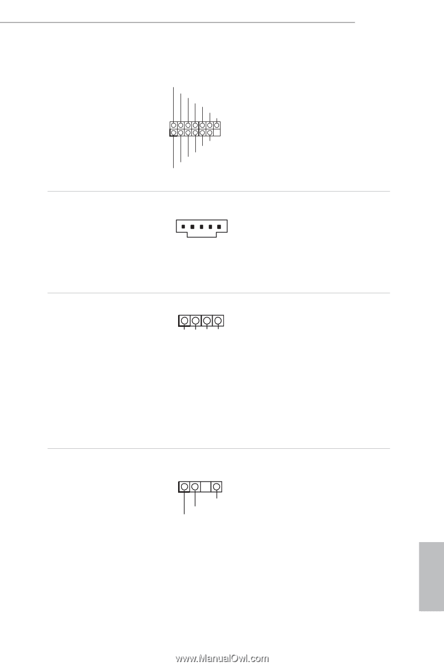
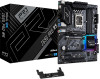
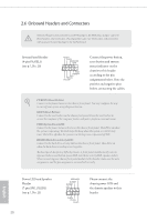
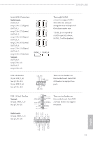
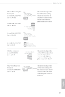
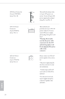
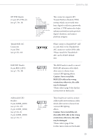
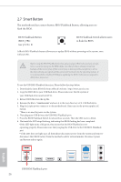
Z690 Pro RS SPI TPM Header (13-pin SPI_TPM_J1) (see p.7, No. 19) Thunderbolt AIC Connector (5-pin TB1) (see p.7, No. 28) RGB LED Header (4-pin RGB_LED1) (see p.7, No. 30) Addressable LED Headers (3-pin ADDR_LED1) (see p.7, No. 29) (3-pin ADDR_LED2) (see p.7, No. 8) (3-pin ADDR_LED3) (see p.7, No. 7) SPI_DQ3 SPI_PWR Dummy CLK SPI_MOSI RST# TPM_PIRQ 1 SPI_TPM_CS# GND RSMRST# SPI_MISO SPI_CS0 SPI_DQ2 This connector supports SPI Trusted Platform Module (TPM) system, which can securely store keys, digital certificates, passwords, and data. A TPM system also helps enhance network security, protects digital identities, and ensures platform integrity. Please connect a Thunderbolt™ addin card (AIC) to the Thunderbolt AIC connector via the GPIO cable. *Please install the Thunderbolt™ AIC card to PCIE5 (default slot). 1 12V G R B This RGB header is used to connect RGB LED extension cable which allow users to choose from various LED lighting effects. Caution: Never install the RGB LED cable in the wrong orientation; otherwise, the cable may be damaged. *Please refer to page 54 for further instructions on this header. 1 GND DO_ADDR VOUT These headers are used to connect Addressable LED extension cables which allow users to choose from various LED lighting effects. Caution: Never install the Addressable LED cable in the wrong orientation; otherwise, the cable may be damaged. *Please refer to page 55 for further instructions on this header. 25 English
-
 1
1 -
2
-
3
-
4
-
5
-
6
-
7
-
8
-
9
-
10
-
11
-
12
-
13
-
14
-
15
-
16
-
17
-
18
-
19
-
20
-
21
-
22
-
23
-
24
-
25
-
26
-
27
-
 28
28 -
 29
29 -
 30
30 -
 31
31 -
 32
32 -
 33
33 -
 34
34 -
 35
35 -
 36
36 -
 37
37 -
 38
38 -
39
-
40
-
41
-
42
-
43
-
44
-
45
-
46
-
47
-
48
-
49
-
50
-
51
-
52
-
53
-
54
-
55
-
56
-
57
-
58
-
59
-
60
-
61
-
62
-
63
-
64
-
65
-
66
-
67
-
68
-
69
-
70
-
71
-
72
-
73
-
74
-
75
-
76
-
77
-
78
-
79
-
80
-
81
-
82
-
83
-
84
-
85
-
86
-
87
-
88
-
89
-
90
-
91
-
92
-
93
-
94
-
95
-
96
-
97
-
98
-
99
-
100
-
101
-
102
-
103
-
104
-
105
-
106
-
107
-
108
-
109
-
110
-
111
 |
 |