ASRock Z97 Extreme9 User Manual - Page 28
time, use Intel® Z97 SATA, Serial ATA Express
 |
View all ASRock Z97 Extreme9 manuals
Add to My Manuals
Save this manual to your list of manuals |
Page 28 highlights
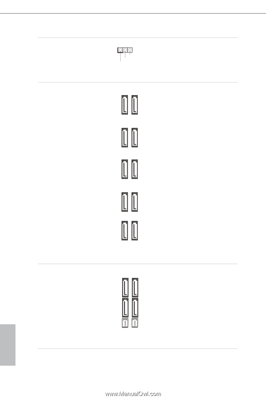
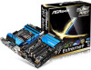
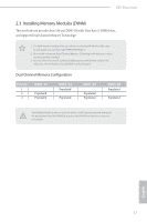
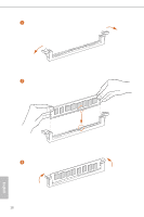
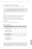
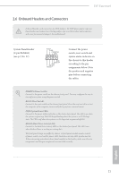
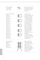
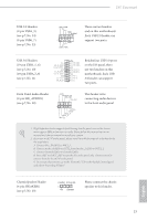
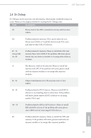
Power LED Header (3-pin PLED1) (see p.7, No. 28) Serial ATA3 Connectors (SATA3_0: see p.7, No. 16) (SATA3_1: see p.7, No. 18) (SATA3_2: see p.7, No. 20) (SATA3_3: see p.7, No. 17) (SATA3_4: see p.7, No. 19) (SATA3_5: see p.7, No. 21) (SATA3_A1: see p.7, No. 13) (SATA3_A2: see p.7, No. 12) (SATA3_A3: see p.7, No. 15) (SATA3_A4: see p.7, No. 14) Serial ATA Express Connectors (SATAE_1: see p.7, No. 23) (SATAE_2: see p.7, No. 22) SATAE_2 SATA3_2 SATA3_1 SATAE_1 SATA3_5 SATA3_4 SATA3_2 SATA3_1 SATA3_0 SATA3_A4 SATA3_A2 1 PLED- PLED+ PLED+ SATA3_5 SATA3_4 SATA3_3 SATA3_A3 SATA3_A1 Please connect the chassis power LED to this header to indicate the system's power status. These ten SATA3 connectors support SATA data cables for internal storage devices with up to 6.0 Gb/s data transfer rate. If the eSATA port on the rear I/O has been connected, the internal SATA3_A4 will not function. The SATA3_1, SATA3_2 are shared with the SATA Express connector (SATAE_2). The SATA3_4, SATA3_5 are shared with the SATA Express connector (SATAE_1). To minimize the boot time, use Intel® Z97 SATA ports (SATA3_0) for your bootable devices. Please connect either SATA or PCIe storage devices to this connector. The lower SATA Express connector (the combination of SATAE_1, SATA3_4, and SATA3_5) is shared with the M.2 Socket (M2_2). English 22
-
 1
1 -
2
-
3
-
4
-
5
-
6
-
7
-
8
-
9
-
10
-
11
-
12
-
13
-
14
-
15
-
16
-
17
-
18
-
19
-
20
-
21
-
22
-
 23
23 -
 24
24 -
 25
25 -
 26
26 -
 27
27 -
 28
28 -
 29
29 -
 30
30 -
 31
31 -
 32
32 -
 33
33 -
34
-
35
-
36
-
37
-
38
-
39
-
40
-
41
-
42
-
43
-
44
-
45
-
46
-
47
-
48
-
49
-
50
-
51
-
52
-
53
-
54
-
55
-
56
-
57
-
58
-
59
-
60
-
61
-
62
-
63
-
64
-
65
-
66
-
67
-
68
-
69
-
70
-
71
-
72
-
73
-
74
-
75
-
76
-
77
-
78
-
79
-
80
-
81
-
82
-
83
-
84
-
85
-
86
-
87
-
88
-
89
-
90
-
91
-
92
-
93
-
94
-
95
-
96
-
97
-
98
-
99
-
100
-
101
-
102
-
103
-
104
-
105
-
106
-
107
-
108
-
109
-
110
-
111
-
112
-
113
-
114
-
115
-
116
-
117
-
118
-
119
-
120
-
121
-
122
-
123
-
124
-
125
 |
 |