Acer ConceptD 500 User Manual
Acer ConceptD 500 Manual
 |
View all Acer ConceptD 500 manuals
Add to My Manuals
Save this manual to your list of manuals |
Acer ConceptD 500 manual content summary:
- Acer ConceptD 500 | User Manual - Page 1
ConceptD 500 User Manual - Acer ConceptD 500 | User Manual - Page 2
are for reference only and may contain information or features that do not apply to your computer. Acer Group shall not be liable for technical or editorial errors or omissions contained in this manual. The terms HDMI and HDMI High-Definition Multimedia Interface, and the HDMI Logo are trademarks or - Acer ConceptD 500 | User Manual - Page 3
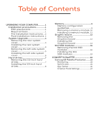
ESD precautions 1 Required tools 1 Pre-installation instructions.....2 Post-installation instructions ..2 System Upgrade 3 Removing the rear system the M.2 SSD modules 19 CONCEPT D PALETTE 23 ConceptD Palette Features .........23 Monitoring 24 Split Screen 25 App Center 26 Creative - Acer ConceptD 500 | User Manual - Page 4
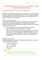
0 - UPGRADING YOUR COMPUTER Upgrading your Computer In this section, you will find: • Instructions on how to replace a hardware component - Acer ConceptD 500 | User Manual - Page 5
that you read the following sections. These sections contain important ESD precautions along with pre-installation and post-installation instructions. ESD precautions Electrostatic discharge (ESD) can damage your processor, disk drives, expansion boards, and other components. Always observe the - Acer ConceptD 500 | User Manual - Page 6
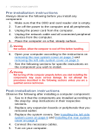
may cause serious damage. Do not attempt the procedures described in the following sections unless you are a qualified service technician. Post-installation instructions Observe the following after installing a computer component: 1. See to it that the components are installed according to the - Acer ConceptD 500 | User Manual - Page 7
system cover 1. Before you proceed, make sure that you have turned off your computer and all peripherals connected to it. Read the Pre-installation instructions on page 2. 2. Remove the screw that secure the rear system cover to the computer. 3. Take off the rear system cover. 4. Set the cover - Acer ConceptD 500 | User Manual - Page 8
(1). 2. Push the rear system cover until it latches into place (2). 3. Secure the rear system cover to the computer using one screw. 4. Observe the Post-installation instructions on page 2. - Acer ConceptD 500 | User Manual - Page 9
UPGRADING YOUR COMPUTER - 5 Removing the left side system cover 1. Remove the two screws that secure the left side system cover to the computer (1). 2. Slide the cover toward the back of the computer and pull away from the side of the computer (2). 3. Set the cover aside for re-installation later. - Acer ConceptD 500 | User Manual - Page 10
6 - UPGRADING YOUR COMPUTER Installing the left side system cover 1. Align the cover to the sides of the computer and slide the cover toward the front of the computer (1). 2. Secure the cover with two screws (2). 3. Observe the Post-installation instructions on page 2. - Acer ConceptD 500 | User Manual - Page 11
UPGRADING YOUR COMPUTER - 7 Hard drives The computer supports installation of two 3.5-inch SATA hard drives in the internal HDD cage. Removing the 3.5-inch hard drives 1. Perform the Pre-installation instructions on page 2. 2. Pull and remove the hard drives from the chassis. 3. Pull both sides of - Acer ConceptD 500 | User Manual - Page 12
hard drive into the carrier (1) and reinsert the retaining screws into the hard drive (2). 3. Insert the hard drives into the chassis. 4. Observe the Post-installation instructions on page 2. - Acer ConceptD 500 | User Manual - Page 13
Memory UPGRADING YOUR COMPUTER - 9 The computer has four DDR4 U-DIMM slots that support up to 64 GB maximum system memory. Memory configuration guidelines To ensure data integrity, use only Acer-approved DDR4 3200 MHz type memory modules. Memory modules must be installed starting with DIMM1 - Acer ConceptD 500 | User Manual - Page 14
10 - UPGRADING YOUR COMPUTER Removing a memory module 1. Perform the Pre-installation instructions on page 2. 2. Remove the graphics board. See Removing the graphics board on page 12. 3. Press outward the holding clips on both sides of the DIMM - Acer ConceptD 500 | User Manual - Page 15
slot. 5. Repeat steps 1~4 to install the other memory modules. 6. Replace the graphics board. See Installing the graphics board on page 14. 7. Observe the Post-installation instructions on page 2. - Acer ConceptD 500 | User Manual - Page 16
in the PCIE x16 slots. The detail configuration will be differed by different models. Removing the Graphics board 1. Perform the Pre-installation instructions on page 2. 2. Disconnect the power cables from the graphics board. 3. Remove the three screws that secures the graphics board to the chassis - Acer ConceptD 500 | User Manual - Page 17
UPGRADING YOUR COMPUTER - 13 4. Unlatch the metal clip that secure the graphics board to the chassis. 5. Release the latch that secures the graphics board to the mainboard (1). 6. Detach the graphics board from the PCIE x16 slot (2). - Acer ConceptD 500 | User Manual - Page 18
14 - UPGRADING YOUR COMPUTER Installing the Graphics board 1. Remove the new graphics board from its packaging. 2. Insert the graphics boards into the PCIE x16 slot and press it down until it latches into place. Note For replace/upgrade graphic board, please check the specification of graphic board - Acer ConceptD 500 | User Manual - Page 19
UPGRADING YOUR COMPUTER - 15 4. Secure the graphics board to the chassis using three screws. 5. Connect the power cables to the graphics board. 6. Observe the Post-installation instructions on page 2. - Acer ConceptD 500 | User Manual - Page 20
M.2 SSD modules The computer contains two M.2 SSD modules installed in the M.2 PCIE slots. Removing the M.2 SSD modules 1. Perform the Pre-installation instructions on page 2. 2. Remove the graphics board. See Removing the graphics board on page 12. 3. Remove the screw that secures the M.2 SSD - Acer ConceptD 500 | User Manual - Page 21
UPGRADING YOUR COMPUTER - 17 5. Remove the thermal pad from the SSD2 slot. 6. Remove the screw that secures the M.2 SSD module from the SSD1 slot. - Acer ConceptD 500 | User Manual - Page 22
18 - UPGRADING YOUR COMPUTER 7. Detach the M.2 SSD module from the SSD1 slot. 8. Remove the thermal pad from the SSD1 slot. - Acer ConceptD 500 | User Manual - Page 23
UPGRADING YOUR COMPUTER - 19 Installing the M.2 SSD modules 1. Remove the new M.2 SSD modules from their packaging. 2. Place a thermal pad into the SSD1 slot. 3. Insert the M.2 SSD module into the SSD1 slot. - Acer ConceptD 500 | User Manual - Page 24
20 - UPGRADING YOUR COMPUTER 4. Secure the M.2 SSD module to the SSD1 slot using one screw. 5. Place a thermal pad into the SSD2 slot. - Acer ConceptD 500 | User Manual - Page 25
UPGRADING YOUR COMPUTER - 21 6. Insert the M.2 SSD module into the SSD2 slot. 7. Secure the M.2 SSD module to the SSD2 slot using one screw. 8. Replace the graphics board. See Installing the graphics board on page 14. 9. Observe the Post-installation instructions on page 2. - Acer ConceptD 500 | User Manual - Page 26
22 - CONCEPT D PALETTE ConceptD Palette In this section, you will find: • Information on how to use the ConceptD Palette software - Acer ConceptD 500 | User Manual - Page 27
) Split Screen App Center Creative Tools Settings To set up the ConceptD Palette application (Windows 10): 1. From the Start menu, select All apps. 2. Select Acer. 3. Select ConceptD Palette. Alternatively, you can double-click the ConceptD Palette desktop shortcut to run the application. - Acer ConceptD 500 | User Manual - Page 28
24 - CONCEPT D PALETTE Monitoring Select the Monitoring tab to view CPU, GPU and system performance. Category CPU GPU System Description Displays CPU temperature and loading. Displays GPU temperature and loading. Displays temperature and loading. Also displays RAM, Wi-Fi and LAN usage. - Acer ConceptD 500 | User Manual - Page 29
Split Screen CONCEPT D PALLETE - 25 Select the Split Screen tab to configure your screen display. Category Split Screen Description Shows options on various split screen configurations. - Acer ConceptD 500 | User Manual - Page 30
26 - CONCEPT D PALETTE App Center Select the App Center tab to view the applications that are avilable for quick access. You can add frequently used applications to this tab by clicking the "+" sign. Category App Icon + Description Displays applications available for quick access/executions. Add - Acer ConceptD 500 | User Manual - Page 31
Creative Tools Settings CONCEPT D PALLETE - 27 Select the Creative Tools Settings tab to configure frequently used design tools. Category Description Screen Snip Settings Configure screen snip setting options. Clipboard Settings Configure clipboard setting options. Color Picker Configure
-
 1
1 -
 2
2 -
 3
3 -
 4
4 -
 5
5 -
 6
6 -
 7
7 -
8
-
9
-
10
-
11
-
12
-
13
-
14
-
15
-
16
-
17
-
18
-
19
-
20
-
21
-
22
-
23
-
24
-
25
-
26
-
27
-
28
-
29
-
30
-
31
 |
 |

ConceptD 500
User Manual