Acer LX.EDV0Z.001 Service Guide - Page 122
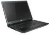
Bottom View
 |
UPC - 884483697694
View all Acer LX.EDV0Z.001 manuals
Add to My Manuals
Save this manual to your list of manuals |
Page 122 highlights
Bottom View CN9 / LAN Conn U24 DIS HDCP ROM U23 Dis Spectrum IC U27 / N10 VGA IC U25 / U27 Dis VRAM IC. U9 / CRT Switch IC CN11 / CRT Conn CN14 /FAN Conn CN15 / HDMI Conn. CN16 / USB CN18 / EXT Mic conn CN21 / EXT HP U31 SPK Amplify IC U21 / LAN transformer PJ2/ PWR Jack conn. PJ1 Battery Conn U18 Card reader U33 Codec IC PU8 VGA 1.1V U22 / CPU socket PU6/ CPU core PU7/ +1.05V PWM CN12, CN13 / Memory DIMM CN10 ODD Conn U28 N.B. CN17 HDD Conn CN19 Mini card Conn U32 SB PU10/ 3V/5V PWM IC 112 Chapter 5