Acer P5230 User Manual - Page 14
Rear side, How to Install Acer Wireless Projection Kit UWA3
 |
View all Acer P5230 manuals
Add to My Manuals
Save this manual to your list of manuals |
Page 14 highlights
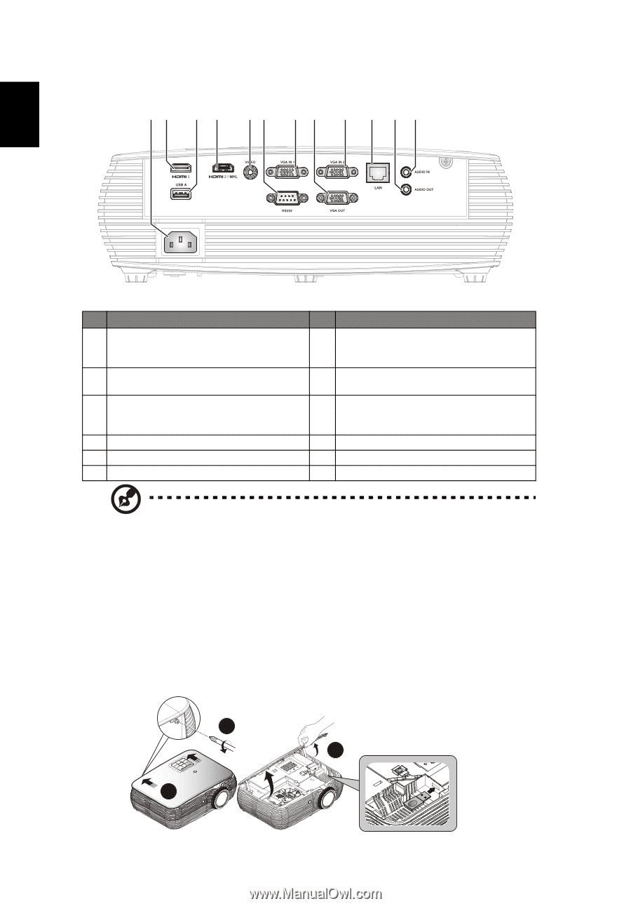
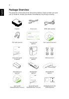
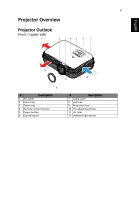
4 Rear side 1 2 3 4 5 6 7 8 7 9 10 11 English # Description # Description 1 Power socket 7 PC analog signal/HDTV/component video input connector (VGA IN 1, VGA IN 2) 2 HDMI 1 connector 8 Monitor loop-through output connector (for VGA IN 1 only) USB connector (device charge and USB 9 3 displays and upport mouse page up/ LAN (RJ45 Port for 10/100M Ethernet) down function) 4 HDMI 2/MHL connector 10 Audio out connector 5 Composite video input connector 11 Audio in connector 6 RS232 connector Note: Functions vary depending on model definition. How to Install Acer Wireless Projection Kit (UWA3) If you had purchased Acer Wireless Projection Kit (UWA3), please follow the below installation steps: 1 Use a screwdriver to remove the screw from the cover. (Illustration #a) 2 Push the cover toward the rear side of projector. (Illustration #b) 3 Open the top cover. (Illustration #c) 4 Install dongle (Illustration #d) a b WIRELESS DONGLE c WIRELESS DONGLE
-
 1
1 -
2
-
3
-
4
-
5
-
6
-
7
-
8
-
 9
9 -
 10
10 -
 11
11 -
 12
12 -
 13
13 -
 14
14 -
 15
15 -
 16
16 -
 17
17 -
 18
18 -
 19
19 -
20
-
21
-
22
-
23
-
24
-
25
-
26
-
27
-
28
-
29
-
30
-
31
-
32
-
33
-
34
-
35
-
36
-
37
-
38
-
39
-
40
-
41
-
42
-
43
-
44
-
45
-
46
-
47
-
48
-
49
-
50
-
51
-
52
-
53
-
54
-
55
-
56
-
57
-
58
-
59
-
60
-
61
-
62
-
63
-
64
-
65
-
66
-
67
-
68
 |
 |