Acer VG271P User Manual - Page 15
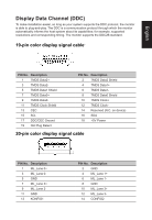
Display Data Channel (DDC), 19-pin color display signal cable*
 |
View all Acer VG271P manuals
Add to My Manuals
Save this manual to your list of manuals |
Page 15 highlights
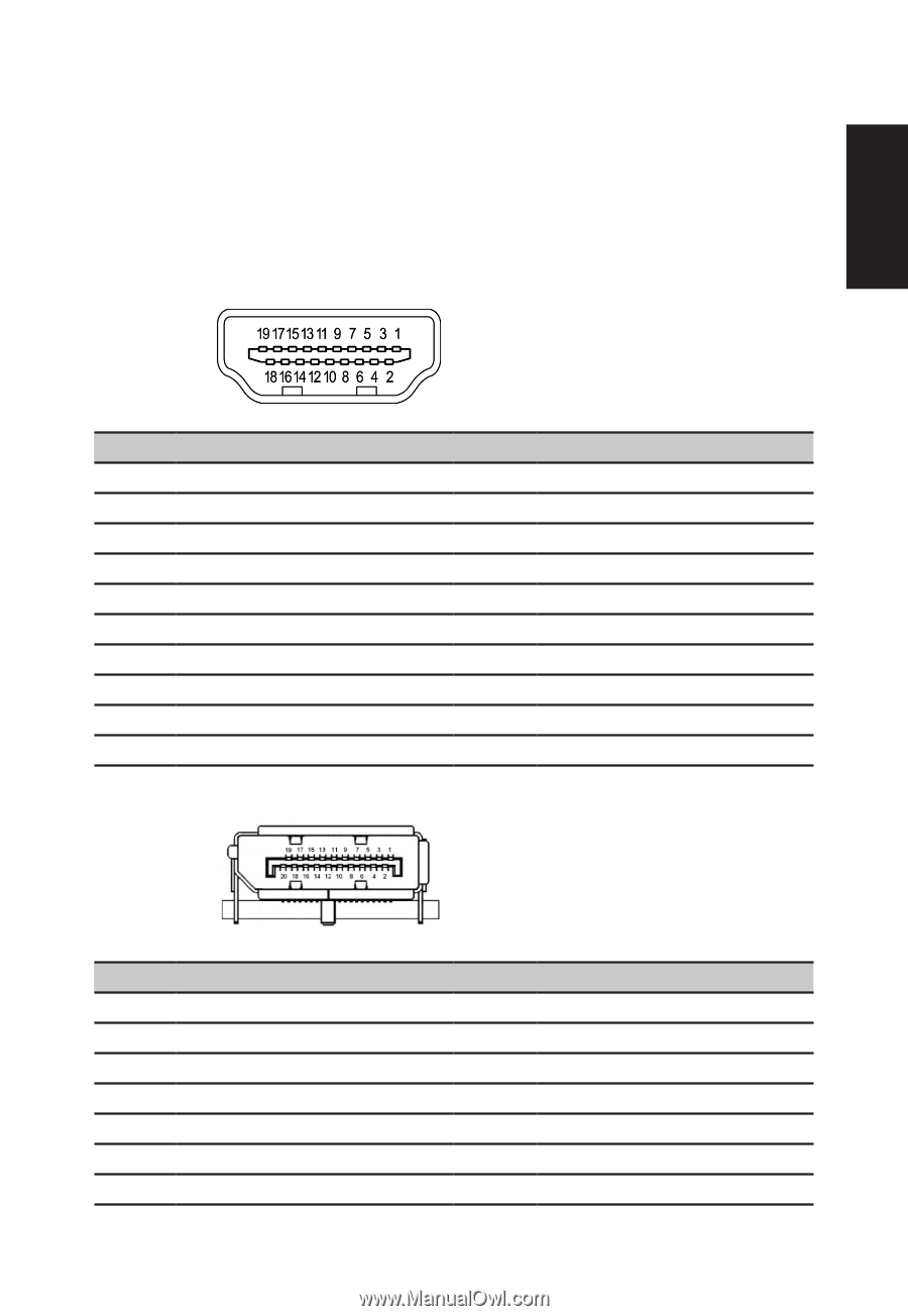
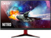
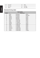
English Display Data Channel (DDC) To make installation easier, so long as your system supports the DDC protocol, the monitor is able to plug-and-play. The DDC is a communication protocol through which the monitor automatically informs the host system about its capabilities; for example, supported resolutions and corresponding timing. The monitor supports the DDC2B standard. 19-pin color display signal cable* PIN No. Description 1 TMDS Data2+ 3 TMDS Data25 TMDS Data1 Shield 7 TMDS Data0+ 9 TMDS Data011 TMDS Clock Shield 13 CEC 15 SCL 17 DDC/CEC Ground 19 Hot Plug Detect PIN No. Description 2 TMDS Data2 Shield 4 TMDS Data1+ 6 TMDS Data18 TMDS Data0 Shield 10 TMDS Clock+ 12 TMDS Clock14 Reserved (N.C. on device) 16 SDA 18 +5V Power 20-pin color display signal cable PIN No. Description 1 ML_Lane 0+ 3 ML_Lane 05 GND 7 ML_Lane 2+ 9 ML_Lane 211 GND 13 KONFIG1 PIN No. Description 2 GND 4 ML_Lane 1+ 6 ML_Lane 18 GND 10 ML_Lane 3+ 12 ML_Lane 314 CONFIG2
-
 1
1 -
2
-
3
-
4
-
5
-
6
-
7
-
8
-
9
-
 10
10 -
 11
11 -
 12
12 -
 13
13 -
 14
14 -
 15
15 -
 16
16 -
 17
17 -
 18
18 -
 19
19 -
 20
20 -
21
-
22
-
23
-
24
-
25
-
26
-
27
-
28
 |
 |