Acer VG271US User Manual - Page 16
Connector Pin Assignment
 |
View all Acer VG271US manuals
Add to My Manuals
Save this manual to your list of manuals |
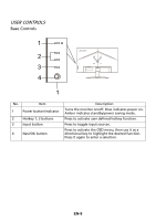
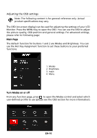
Page 16 highlights
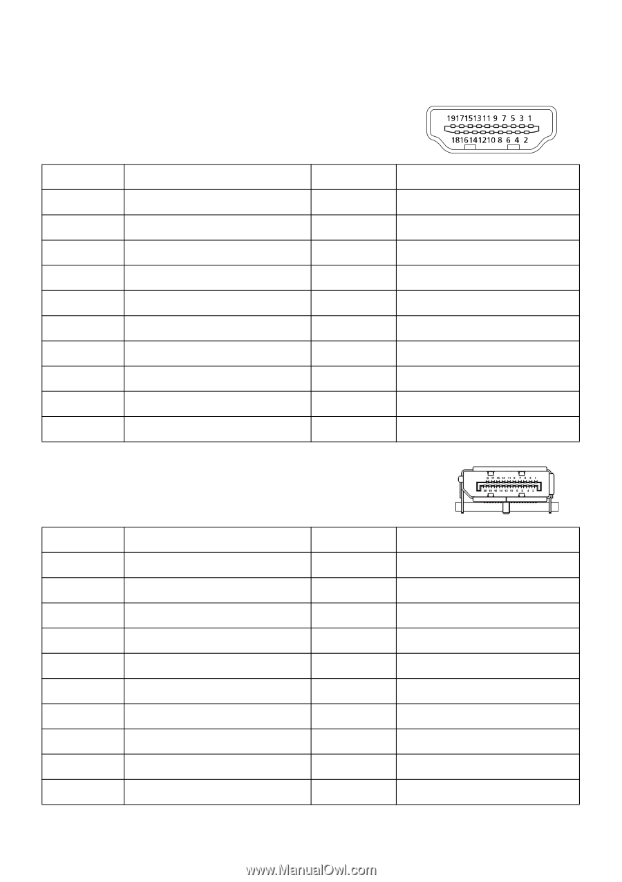
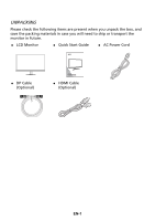
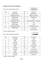
CONNECTOR PIN ASSIGNMENT 19-Pin Color Display Signal Cable* PIN Meaning PIN 1. TMDS Data2+ 10. 2. TMDS Data2 Shield 11. 3. TMDS Data2- 12. 4. TMDS Data1+ 13. 5. TMDS Data1 Shield 14. 6. TMDS Data1- 15. 7. TMDS Data0+ 16. 8. TMDS Data0 Shield 17. 9. TMDS Data0- 18. 19. * only for certain models 20-Pin Color Display Signal Cable* PIN Description 1. Lane0(p) 2. GND 3. Lane0(n) 4. Lane1(p) 5. GND 6. Lane1(n) 7. Lane2(p) 8. GND 9. Lane3(n) 10. Lane3(p) * only for certain models PIN 11. 12. 13. 14. 15. 16. 17. 18. 19. 20. EN-6 Meaning TMDS Clock+ TMDS Clock Shield TMDS Clock- CEC Reserved (N.C. on device) SCL SDA DDC/CEC Ground +5V Power Hot Plug Detect Description GND Lane3(n) Config1 Config2 AUX_CH (n) GND AUX_CH (p) Hot Plug Detect DP Power_Return DP Power
-
 1
1 -
2
-
3
-
4
-
5
-
6
-
7
-
8
-
9
-
10
-
 11
11 -
 12
12 -
 13
13 -
 14
14 -
 15
15 -
 16
16 -
 17
17 -
 18
18 -
 19
19 -
 20
20 -
 21
21 -
22
-
23
-
24
-
25
-
26
-
27
-
28
-
29
-
30
-
31
 |
 |