Adaptec 1520A User Guide - Page 45
Connecting Floppy Drives AHA-1522A only
 |
View all Adaptec 1520A manuals
Add to My Manuals
Save this manual to your list of manuals |
Page 45 highlights
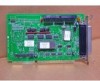
Hardware Installation 3 Daisy chain other external SCSI devices, if any, to the previous device until all devices are connected, as shown in Figure 3-8. Connecting Floppy Drives (AHA-1522A only) The AHA-1522A floppy connector uses a 34-pin floppy ribbon cable with a 34-pin header connector. Be sure to maintain pin-1 orientation, as described in Connecting Internal SCSI Devices on page 3-8. 1 Connect the non-split end of the 34-pin floppy ribbon cable to the floppy connector, as shown in Figure 3-11. Colored stripe Floppy ribbon cable Pin 1 Floppy connector Figure 3-11. Connecting Floppy Cable to Host Adapter 3-11 AAAAAAAAAAAAAAAAAASPCAAAAAArtuHoiAAArncAAAArtkAAAe-SAAAn1NAAApt5AAAeuD1AAAcmAAA0aAAANtAbeAAAeu:/AAAr2mAAA1:0AAA15bAAAA/1eAAA1rAAA0S8:AAA4/e4AAA90rAAA94i0eAAA1-AAAs08AAAU04AAA,2AAAsR-AAAe0AAAre0'AAAvsAAA.AAAGCAAAuAAAAAAidAAAeAAAAAAAAAEAAACAAAAAANAAAAAADAAAAAAaAAAtAAAePAAA: aAAA1gAAA1AAAe/AAA:2AAA39AAA-/AAA91AAA41AAAAAAAAAAAAAAAAAAAA
-
 1
1 -
2
-
3
-
4
-
5
-
6
-
7
-
8
-
9
-
10
-
11
-
12
-
13
-
14
-
15
-
16
-
17
-
18
-
19
-
20
-
21
-
22
-
23
-
24
-
25
-
26
-
27
-
28
-
29
-
30
-
31
-
32
-
33
-
34
-
35
-
36
-
37
-
38
-
39
-
 40
40 -
 41
41 -
 42
42 -
 43
43 -
 44
44 -
 45
45 -
 46
46 -
 47
47 -
 48
48 -
 49
49 -
 50
50 -
51
-
52
-
53
-
54
-
55
-
56
-
57
-
58
-
59
-
60
-
61
-
62
 |
 |
