Airlink ASW324 Quick Installation Guide - Page 2
Introduction, 1 Hardware Interface, 2 Panel - switch
 |
View all Airlink ASW324 manuals
Add to My Manuals
Save this manual to your list of manuals |
Page 2 highlights
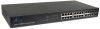
1 Introduction Congratulations on your purchase of the 24-Port 10/100Mbps Fast Ethernet Switch! It is an easy-installed network switch which helps you to extend your network structure quickly and reliably. Purpose This Quick Installation Guide tells you how to install your Switch and how to connect it to your Ethernet network. Terms/Usage In this manual, the term "Switch" (first letter upper case) refers to your 24-Port 10/100Mbps Fast Ethernet Switch, and "switch" (first letter lower case) refers to other Ethernet switches. 1.1 Hardware Interface • 24-Port 10/100Mbps auto-negotiation RJ45 Ports • All ports support auto MDI/MDIX, no need to use cross-over cables 2 1.2 Panel 1.2.1 Front Panel The front panel of the Switch consists of LED indicators, and 24 10/100Mbps ports. The figure below shows the front panel of the Switch. Figure 1-1 Front Panel view of the Switch • 10/100Mbps Ports (Port 1~24): These ports support 10/ 100Mbps, and can operate in Half/Full Duplex transfer modes. These ports also support automatic MDI/MDI-X crossover detection, giving true "plug and play" capability. • LED Indicators: Comprehensive LED indicators display the status of the switch and the network (see Section 1.2.3). 1.2.2 Rear Panel Figure 1-2 Rear Panel view of the Switch • AC Power Connector: Supports AC 100~240V, 50~60Hz. 3
-
 1
1 -
 2
2 -
 3
3 -
 4
4 -
 5
5
 |
 |
