Airlink ASW324 Quick Installation Guide - Page 3
Technical Specifications
 |
View all Airlink ASW324 manuals
Add to My Manuals
Save this manual to your list of manuals |
Page 3 highlights
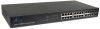
NOTICE: Do not envelop Radiator Fan while the Switch is working. 1.2.3 LED indicators information The front panel LEDs provide instant status feedback and help monitoring and troubleshooting when needed. Figure 1-3 Front Panel view of the switch • POWER: Power Indicator LED POWER Color Green Solid The Switch is power-on Status Blinking N/A Off No power 4 • Port 1~24 10/100M Status LEDs LED LINK/ ACT LED 10/100 M Color Green Solid The respective port is successfully connected to an Ethernet network. Color Green Solid The respective port is connected to the 100Mbps Ethernet network. Status Blinking The port is transmitting or receiving data on the Ethernet network. Status Blinking N/A Off No link Off The respective port is connected to the 10Mbps Ethernet network, or no link. 1.3 Technical Specifications Standards • IEEE 802.3 10BASE-T, IEEE 802.3u 100BASE-TX and IEEE 802.3x Flow Control Network Cables • Ethernet: Cables: 2-pair UTP Cat. 3, 4, 5, Twisted Pair (UTP) 5
-
 1
1 -
 2
2 -
 3
3 -
 4
4 -
 5
5
 |
 |
