Airlink ASW408POE Quick Installation Guide - Page 2
Package Contents, 2 Panel
 |
View all Airlink ASW408POE manuals
Add to My Manuals
Save this manual to your list of manuals |
Page 2 highlights
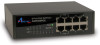
1.1 Package Contents • 1 x ASW408POE • 1 x Switching Power Adapter • 1 x Quick Installation Guide • 4 x Rubber foot for shock cushioning 1.2 Panel 1.2.1 Front Panel The picture below depicts the front panel of the PoE Switch: Figure 1-1 Front Panel view of the Switch • PoE Ports (Port 1~4) These ports are 802.3af PoE enabled ports, the PoE port will automatically activate when a compatible terminal is identified. The PoE switch will distribute power through the Ethernet ports to the connected PoE device. For devices that are not compatible, the PoE port will not supply the power to this device. This feature allows user's to freely and safely utilize the 802.3af PoE for Power over Lan devices on their network. • Ethernet Ports (Port 5~8) These ports support network speeds of either 10Mbps or 100Mbps, and can operate in half and full-duplex transfer modes. These ports also support automatic MDI/MDIX crossover detection, which give the PoE switch "plug and play" capabilities. Just simply connect any network cable between the PoE switch and the device and it will automatically detect the settings of the device and adjust itself 2 accordingly • LED Indicators Comprehensive LED indicators display the status of the switch and the network (see Section 1.2.3). 1.2.2 Rear Panel Figure 1-2 Rear Panel view of the Switch • Power Adapter Connector: DC 48V/0.8A, AC 100~240V, 50~60Hz 1.2A 1.2.3 LED indicators information The front panel LEDs provide instant status feedback and help monitoring and troubleshooting when needed. • Power: Power Indicator LED Power Color Green Solid The Switch is power-on Status Blinking N/A Off No power • Max. PoE: Max. PoE Power Indicator 3
-
 1
1 -
 2
2 -
 3
3 -
 4
4
 |
 |
