Akai MPK88 Operation Manual - Page 20
Aftertouch Parameters, Midi Channel Field, Minimum Range Field
 |
View all Akai MPK88 manuals
Add to My Manuals
Save this manual to your list of manuals |
Page 20 highlights
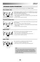
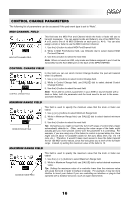
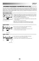
AFTERTOUCH PARAMETERS For some applications, you might wish to use the faders or knobs as Aftertouch controllers. In this scenario, the knob or fader will be transmitting Aftertouch information which could be used to control, say, a vibrato of a device that the MPK61/MPK88 is controlling. The following list of parameters can be accessed if "Aftertouch" is selected as the event type for the selected knob or fader. MIDI CHANNEL FIELD MIDI PORT/CHANNEL FIELD This field sets the MIDI Port and Channel which the knob or fader will use to transmit messages. You can assign knobs and faders to one of two MIDI Ports, A or B, and to one of 16 MIDI Channels on each port (i.e. A14). You can also assign a knob or fader to use the MIDI Common Channel. 1. Use the [] button to select the next field. Note: When not used via USB, only knobs and faders assigned to port A will be transmitted via the 5-pin MIDI port on the back of the MPK61/MPK88. MINIMUM RANGE FIELD This field is used to specify the minimum value that the aftertouch will transmit. 1. Use [] buttons to select Minimum Range field. 2. While in Minimum Range field, use [VALUE] dial to select desired minimum aftertouch value. 3. Use the [>] button to select the next field. MINIMUM RANGE FIELD MAXIMUM RANGE FIELD This field is used to specify the maximum value that the knob or fader can output. 1. Use the [] buttons to select Maximum Range field. 2. While in Maximum Range field, use [VALUE] dial to select desired maximum value. MAXIMUM RANGE FIELD 17
-
 1
1 -
2
-
3
-
4
-
5
-
6
-
7
-
8
-
9
-
10
-
11
-
12
-
13
-
14
-
 15
15 -
 16
16 -
 17
17 -
 18
18 -
 19
19 -
 20
20 -
 21
21 -
 22
22 -
 23
23 -
 24
24 -
 25
25 -
26
-
27
-
28
-
29
-
30
-
31
-
32
-
33
-
34
-
35
-
36
-
37
-
38
-
39
-
40
-
41
-
42
-
43
-
44
 |
 |
