Akai PDP4206EM Service Manual - Page 38
Akai PDP4206EM - 42" Plasma EDTV Manual
 |
UPC - 827935510257
View all Akai PDP4206EM manuals
Add to My Manuals
Save this manual to your list of manuals |
Page 38 highlights
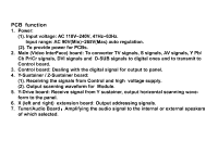
PCB function 1. Power: (1). Input voltage: AC 110V~240V, 47Hz~63Hz. Input range: AC 90V(Min)~265V(Max) auto regulation. (2). To provide power for PCBs. 2. Main (Video InterFace) board: To converter TV signals, S signals, AV signals, Y Pb/ Cb Pr/Cr signals, DVI signals and D-SUB signals to digital ones and to transmit to Control board. 3. Control board: Dealing with the digital signal for output to panel. 4. Y-Sustainer / Z-Sustainer board: (1). Receiving the signals from Control and high voltage supply. (2). Output scanning waveform for Module. 5. Y-Drive board: Receive signal from Y sustainer, output horizontal scanning waveform to the panel. 6. X (left and right) extension board: Output addressing signals. 7. Tuner/Audio Board: Amplifying the audio signal to the internal or external speakers of which selected.
-
 1
1 -
2
-
3
-
4
-
5
-
6
-
7
-
8
-
9
-
10
-
11
-
12
-
13
-
14
-
15
-
16
-
17
-
18
-
19
-
20
-
21
-
22
-
23
-
24
-
25
-
26
-
27
-
28
-
29
-
30
-
31
-
32
-
 33
33 -
 34
34 -
 35
35 -
 36
36 -
 37
37 -
 38
38 -
 39
39 -
 40
40 -
 41
41 -
 42
42 -
 43
43 -
44
-
45
-
46
-
47
-
48
-
49
-
50
-
51
-
52
-
53
-
54
-
55
-
56
-
57
-
58
-
59
-
60
-
61
-
62
-
63
-
64
-
65
-
66
-
67
-
68
-
69
-
70
-
71
-
72
-
73
-
74
-
75
-
76
-
77
-
78
-
79
-
80
-
81
-
82
-
83
-
84
-
85
-
86
-
87
-
88
-
89
-
90
-
91
-
92
-
93
-
94
-
95
-
96
-
97
-
98
-
99
-
100
-
101
-
102
-
103
 |
 |
