Amana AGR4230BAW Installation Guide - Page 10
Level Range, Electronic Ignition System
 |
View all Amana AGR4230BAW manuals
Add to My Manuals
Save this manual to your list of manuals |
Page 10 highlights
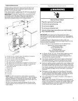
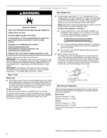
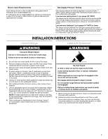
IMPORTANT: If the back of the range is more than 2" (5.1 cm) from the mounting wall, the rear range foot may not engage the bracket. Slide the range forward and determine if there is an obstruction between the range and the mounting wall. Changes to the gas supply must be performed by a qualified service technician. If you need assistance or service, refer to the "Assistance or Service" section of the Use and Care Guide for contact information. 6. Repeat steps 1 and 2 to ensure that the range foot is engaged in the anti-tip bracket. If the rear of the range lifts more than ½" (1.3 cm) off the floor without resistance, the anti-tip bracket may not be installed correctly. Do not operate the range without anti-tip bracket installed and engaged. Please reference the "Assistance or Service" section of the Use and Care Guide or the cover or "Warranty" section of the User Instructions to contact service. Level Range 1. Place a standard flat rack in oven. 2. Place level on the rack, and check levelness of the range, first side to side, then front to back. Check Operation of Cooktop Burners 1. If control panel and knobs were removed earlier, reinstall knobs. 2. Push in and turn each surface unit control knob to IGNITE position. The flame should light within 4 seconds. OFF IGNITE HI LO 8 2 6 4 MED 3. Turn control knob to HI position after burner lights. 4. Check each cooktop burner for proper flame. The small inner cone should have a very distinct blue flame ¼" (0.64 cm) to ½" (1.3 cm) long. The outer cone is not as distinct as the inner cone. A B 3. If range is not level, pull range forward until rear leveling leg is removed from the anti-tip bracket. 4. Use a ³⁄8" drive ratchet and slip-joint pliers to adjust leveling legs up or down until the range is level. 5. Push range back into position. 6. Check that rear leveling leg is engaged in the anti-tip bracket. NOTE: Range must be level for satisfactory baking performance. Electronic Ignition System Initial lighting and gas flame adjustments Cooktop and oven burners use electronic igniters in place of standing pilots. When the cooktop control knob is turned to the "IGNITE" position, the system creates a spark to light the burner. This sparking continues until the control knob is turned to the desired setting. When the oven control is turned to the desired setting, a hot surface igniter heats to a bright orange and ignites the gas. No sparking occurs. The glow bar remains on while the burner operates. 5. Turn the control knob quickly to the LO position after the burner lights. If the flame goes out, turn the control knob to the OFF position. 6. Check each cooktop burner for proper low flame. The low flame should be a minimum, steady blue flame. The flame size should be ¼" to ³⁄8" (0.64 cm to 0.95 cm) high. If the low flame needs adjusting: 1. Turn control knob to the LO setting and remove control knob. 2. Insert a small flat-blade screwdriver into the valve stem. Turn the valve adjusting screw to obtain the smallest flame that will not go out when the control of a cold burner is quickly turned from HI to LO. Turn right to decrease flame height. Turn left to increase flame height. Repeat for other cooktop burners as needed. A A. Valve stem 3. Replace control knob. 10
-
 1
1 -
2
-
3
-
4
-
 5
5 -
 6
6 -
 7
7 -
 8
8 -
 9
9 -
 10
10 -
 11
11 -
 12
12 -
 13
13 -
 14
14 -
 15
15 -
16
 |
 |
