Amana AGR5630BD Installation Instruction - Page 15
To Convert Surface Burners Natural Gas to LP Gas
 |
View all Amana AGR5630BD manuals
Add to My Manuals
Save this manual to your list of manuals |
Page 15 highlights
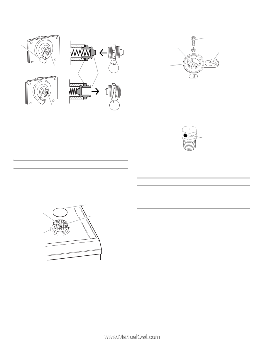
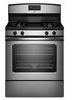
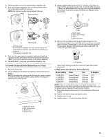
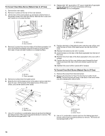
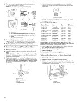
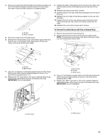
3. Remove plastic cover from gas pressure regulator cap. 4. Turn gas pressure regulator cap counterclockwise with a ⁵⁄₈" combination wrench to remove. NOTE: Do not remove the spring beneath the cap. Side view before A 3. Apply masking tape to the end of a 7 mm nut driver to help hold the gas orifice spud in the nut driver while changing it. Press nut driver down onto the gas orifice spud and remove by turning it counterclockwise and lifting out. Set gas orifice spud aside. C A D NG NG B D E LP LP C Side view after A. Plastic cover B. Gas pressure regulator cap with solid end facing out C. Gas pressure regulator cap with hollow end facing out D. Washer E. Gas pressure regulator cap 5. Turn over the gas pressure regulator cap and reinstall on regulator so that the hollow end faces out and the marking "LP" is facing the direction shown in the above drawing. 6. Replace plastic cover over gas pressure regulator cap. To Convert Surface Burners (Natural Gas to LP Gas) 1. Remove burner cap. 2. Using a Phillips or Quadrex® screwdriver, remove the burner base. NOTE: Reinstall one of the screws through the range cooktop to hold the orifice spud holder in place while removing and replacing the orifice spuds. C A D B B A. Orifice spud B. Orifice spud holder C. Screw D. Spark electrode 4. Remove the cardboard orifice spud holder shipped in the literature package in the oven. Gas orifice spuds are stamped with a number, marked with 1 color dot, and have a groove in the hex area. Replace the Natural gas orifice spud with the correct LP gas orifice spud. A A. LP groove Refer to the following chart for correct LP gas orifice spud placement. LP Gas Orifice Spud Chart for Surface Burners Burner Rating 14,000 BTU 11,000 BTU 8,000 BTU 5,000 BTU Color Yellow/Orange Yellow/Brown Yellow/Black Yellow/White Size 1.07 mm 0.99 mm 0.85 mm 0.70 mm ID Number L107 L99 L85 L70 NOTE: Refer to the Model Number and Serial Number Plate located on the oven frame behind the top left side of the oven door for proper sizing of spuds for each burner location. 5. Place Natural gas orifice spuds in the cardboard orifice spud holder. 6. Replace the burner base using both screw. 7. Replace burner cap. 8. Repeat steps 1-7 for the remaining burners. A. Igniter electrode B. Gas tube opening C. Burner cap D. Burner base 15
-
 1
1 -
2
-
3
-
4
-
5
-
6
-
7
-
8
-
9
-
 10
10 -
 11
11 -
 12
12 -
 13
13 -
 14
14 -
 15
15 -
 16
16 -
 17
17 -
 18
18 -
 19
19 -
 20
20
 |
 |