Amana AGR5630BD Installation Instruction - Page 3
Installation Requirements - parts
 |
View all Amana AGR5630BD manuals
Add to My Manuals
Save this manual to your list of manuals |
Page 3 highlights
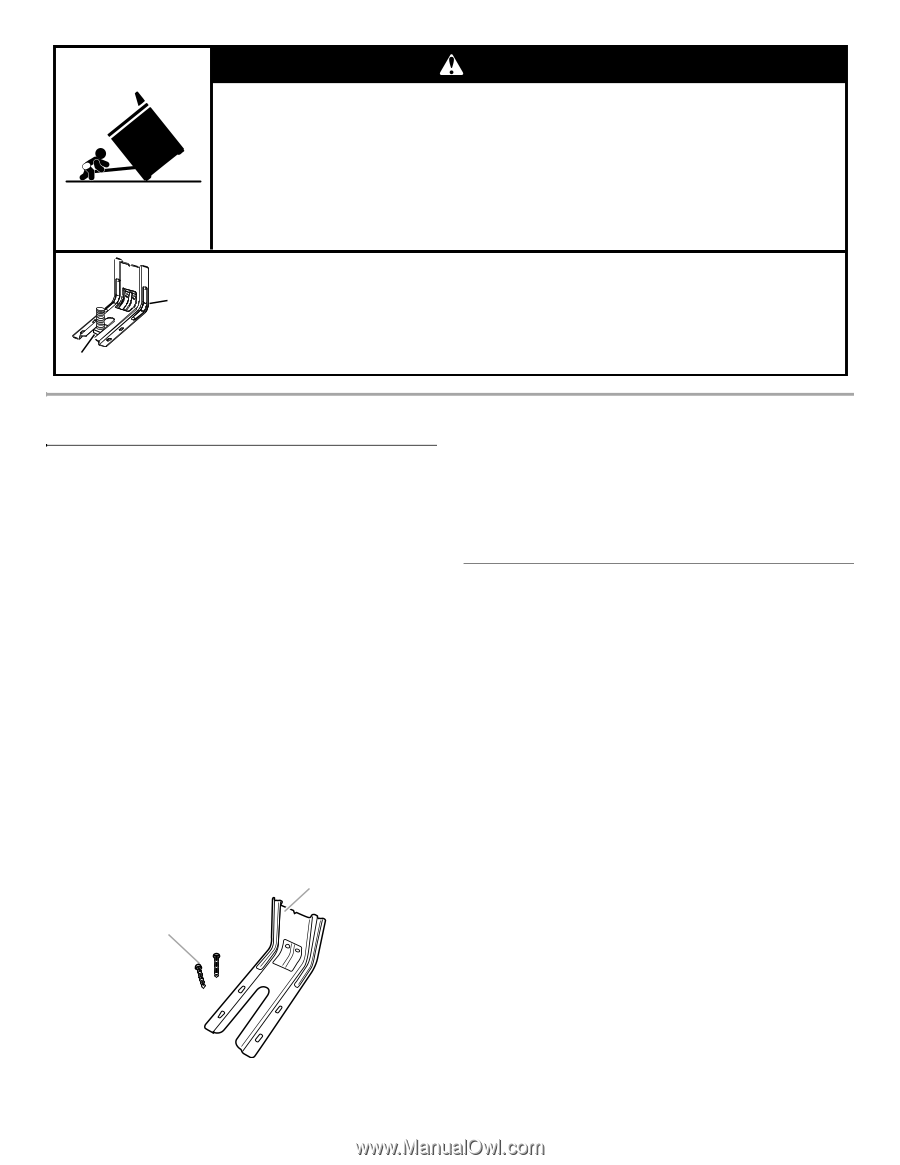
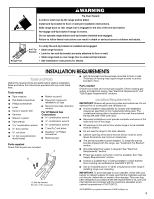
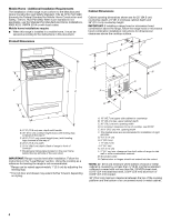
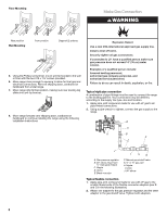
Range Foot WARNING Tip Over Hazard A child or adult can tip the range and be killed. Install anti-tip bracket to floor or wall per installation instructions. Slide range back so rear range foot is engaged in the slot of the anti-tip bracket. Re-engage anti-tip bracket if range is moved. Do not operate range without anti-tip bracket installed and engaged. Failure to follow these instructions can result in death or serious burns to children and adults. Anti-Tip Bracket To verify the anti-tip bracket is installed and engaged: • Slide range forward. • Look for the anti-tip bracket securely attached to floor or wall. • Slide range back so rear range foot is under anti-tip bracket. • See installation instructions for details. INSTALLATION REQUIREMENTS Tools and Parts Gather the required tools and parts before starting installation. Read and follow the instructions provided with any tools listed here. Tools needed ■ Tape measure ■ Flat-blade screwdriver ■ Phillips screwdriver ■ Level ■ Hand or electric drill ■ Hammer ■ Wrench or pliers ■ Pipe wrench combination wrench ■ ¼" drive ratchet nut driver 3.2 mm) drill bit (for wood floors) ■ Marker or pencil ■ Pipe-joint compound resistant to LP gas ■ Noncorrosive leak-detection solution For LP/Natural Gas Conversions combination wrench ■ ½" combination wrench combination wrench ■ 7 mm nut driver ■ Quadrex®† or Phillips screwdriver ■ Masking tape Parts supplied Check that all parts are included. A B A. Anti-tip bracket B. #12 x 1⁵⁄₈" screws (2) ■ Anti-tip bracket must be securely mounted to floor or wall. Thickness of flooring may require longer screws to anchor bracket to floor. Parts needed Check local codes and consult gas supplier. Check existing gas supply and electrical supply. See "Electrical Requirements" and "Gas Supply Requirements" sections. Location Requirements IMPORTANT: Observe all governing codes and ordinances. Do not obstruct flow of combustion and ventilation air. ■ It is the installer's responsibility to comply with installation clearances specified on the model/serial rating plate. The model/serial rating plate is located on the oven frame behind the top left side of the oven door. ■ Recessed installations must provide complete enclosure of the sides and rear of the range. ■ All openings in the wall or floor where range is to be installed must be sealed. ■ Do not seal the range to the side cabinets. ■ Cabinet opening dimensions that are shown must be used. Given dimensions are minimum clearances. ■ The anti-tip bracket must be installed. To install the anti-tip bracket shipped with the range, see "Install Anti-Tip Bracket" section. ■ Grounded electrical supply is required. See "Electrical Requirements" section. ■ Proper gas supply connection must be available. See "Gas Supply Requirements" section. ■ Contact a qualified floor covering installer to check that the floor covering can withstand at least 200°F (93°C). ■ Use an insulated pad or ¼" (0.64 cm) plywood under range if installing range over carpeting. IMPORTANT: To avoid damage to your cabinets, check with your builder or cabinet supplier to make sure that the materials used will not discolor, delaminate or sustain other damage. This oven has been designed in accordance with the requirements of UL and CSA International and complies with the maximum allowable wood cabinet temperatures of 194°F (90°C). †® QUADREX is a registered trademark of NLW Holdings, Inc. 3
-
 1
1 -
 2
2 -
 3
3 -
 4
4 -
 5
5 -
 6
6 -
 7
7 -
 8
8 -
 9
9 -
10
-
11
-
12
-
13
-
14
-
15
-
16
-
17
-
18
-
19
-
20
 |
 |