Ariens Deluxe 30 Owners Manual - Page 13
Remote Deflector Control, NOTICE, IMPORTANT
 |
View all Ariens Deluxe 30 manuals
Add to My Manuals
Save this manual to your list of manuals |
Page 13 highlights
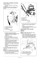
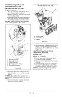
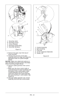
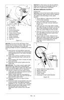
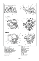
1 8 3 2 6 9 4 5 1. Chute Rod 2. Gear Cover 3. Control Assembly 4. Gear Assembly 5. Chute Control Cable 6. Alignment Marker 7. Chute Pedestal 8. Rubber Grommet 9. Hair Pin Figure 14 9 1 7 NOTICE: To ensure the discharge chute follows its full range of travel, make sure the control lever is centered in the slot and pointing straight up before installing the chute rod. 9. Insert chute rod end without ears into control lever and slide into control panel until opposite end of rod clears the gear assembly. 10. Align end of chute rod with hex hole in gear assembly and insert until ears hit gear. 11. Insert hairpin into hole in chute rod near gear assembly. 12. Hook the chute control cable onto the chute rod. IMPORTANT: The chute control cable hook will prevent the cable from contacting the engine or muffler guard. Make sure this cable stays connected while unit is in operation. 13. Check to make sure the chute control cable ends are properly seated in control assembly and lock arm. 14. Adjust control cable as necessary to remove cable slack. Be sure lock arm is fully seated in gear teeth. 15. Replace gear cover on top of chute pedestal. 16. Orient the chute and pedestal to its most vertical position and tighten pedestal hardware to 15 - 31 lbf-ft (20 - 42 N•m). 17. Make sure the discharge chute rotates left and right when you push the discharge chute control lever left and right. NOTICE: If chute does not stay in position, adjust as directed in Discharge Chute on page 28 or repair before operation. Remote Deflector Control (Figure 15) NOTICE: Connect the barrel cable end to the chute deflector cable anchor before clipping the cable to the discharge chute cable bracket. 1. Route deflector cable along the left side of the chute pedestal. 2. Insert the barrel cable end into the bracket on left side of chute deflector (Figure 15). 3. Hold seal out of the way while routing the cable through the bracket on the left side of the discharge chute, and then push the cable fitting into the bracket. 4. Push the seal securely over the end of the cable fitting to prevent water from entering the cable. 5. Check deflector travel. Adjust nut on cable end under control panel to obtain full travel, if necessary (see Remote Deflector Control Adjustment on page 28). . 2 3 1 3 5 4 1. Chute Deflector Cable Anchor 2. Barrel Cable End 3. Deflector Cable 4. Cable Fitting 5. Discharge Chute Cable Bracket Figure 15 EN - 13
-
 1
1 -
2
-
3
-
4
-
5
-
6
-
7
-
 8
8 -
 9
9 -
 10
10 -
 11
11 -
 12
12 -
 13
13 -
 14
14 -
 15
15 -
 16
16 -
 17
17 -
 18
18 -
19
-
20
-
21
-
22
-
23
-
24
-
25
-
26
-
27
-
28
-
29
-
30
-
31
-
32
-
33
-
34
-
35
-
36
-
37
-
38
-
39
-
40
-
41
-
42
 |
 |
