Ariens Hydro Pro 28 Owners Manual - Page 26
Check Attachment Idler Arm Roller, Clearance, Attachment Clutch Cable
 |
View all Ariens Hydro Pro 28 manuals
Add to My Manuals
Save this manual to your list of manuals |
Page 26 highlights
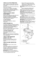
1 2 3 OS7185 OS7191 1. Attachment Clutch Cable 2. Adjustment Barrel 3. Jam Nut Figure 25 5. With the attachment clutch disengaged, check that the attachment idler arm lightly touches the frame (Figure 26). 6. Tighten jam nut on the adjustment barrel. \ With the attachment clutch disengaged, check the attachment idler arm position here. The attachment idler arm should lightly touch the frame. Check Attachment Idler Arm Roller Clearance (Figure 27) NOTE: It will be difficult to check the measurement inside the frame. Use a 1/2" (12.7 mm) minimum spacer as a gauge to check the clearance between the roller and the frame. 1. Place the unit into the service position. Remove the bottom cover. 2. With the clutch lever engaged, check the clearance between the frame and plastic roller on the lower end of the attachment idler arm (Figure 27). • If roller is 1/2 - 7/8" (12.7 - 22.2 mm) from frame, no further adjustments are required. • If roller is less than 1/2" (12.7 mm) from frame, loosen idler adjustment nut and move idler closer to the belt. Tighten adjustment nut and recheck the roller clearance. • If roller is more than 7/8" (22.2 mm) from frame, loosen idler adjustment nut and move idler away from the belt. Tighten adjustment nut and recheck roller clearance. Some components removed for clarity of illustration. 4 1 2 3 Figure 26 OS7196 Roller should be 1/2 - 7/8" (12.7 - 22.2 mm) from the frame when the attachment clutch is engaged. 1. Idler Adjustment Nut 2. Attachment Idler Arm 3. Roller 4. Frame Figure 27 OS7189 EN - 26
-
 1
1 -
2
-
3
-
4
-
5
-
6
-
7
-
8
-
9
-
10
-
11
-
12
-
13
-
14
-
15
-
16
-
17
-
18
-
19
-
20
-
 21
21 -
 22
22 -
 23
23 -
 24
24 -
 25
25 -
 26
26 -
 27
27 -
 28
28 -
 29
29 -
 30
30 -
 31
31 -
32
-
33
-
34
-
35
-
36
-
37
-
38
 |
 |
