Ariens Hydro Pro 28 Owners Manual - Page 9
Chute Control Cable, Discharge Chute Ring
 |
View all Ariens Hydro Pro 28 manuals
Add to My Manuals
Save this manual to your list of manuals |
Page 9 highlights
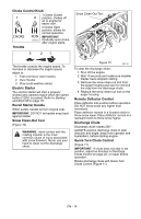
OS7040 1 2 4 1 3 2 5 7 6 4 7 1 5 3 1. Mounting Holes 2. Discharge Chute 3. Discharge Chute Ring 4. Chute Pedestal 5. Mounting Hardware Figure 5 4. Remove the gear cover from top of chute pedestal. 5. Release the lock teeth on the gear assembly with your finger and rotate the discharge chute so it points straight ahead. NOTE: Make sure alignment markers are lined up when discharge chute is pointing straight ahead. 6. Remove rubber grommet from control panel. 7. Make sure the chute control cable is routed between the lower handlebar and the bottom of the control panel, insert control assembly into slot in control panel from below and install assembly into nylon bushing in control panel. 8. Reinstall rubber grommet over control assembly knob and into control panel. 1. Chute Rod 2. Gear Cover 3. Control Assembly 4. Gear Assembly 5. Chute Control Cable 6. Alignment Marker 7. Hair Pin Figure 6 NOTE: To ensure the discharge chute follows its full range of travel, make sure the control lever is centered in the slot and pointing straight up before installing the chute rod. 9. Insert chute rod end without ears into control lever and slide into control panel until opposite end of rod clears the gear assembly. 10. Align end of chute rod with hex hole in gear assembly and insert until ears hit gear. 11. Insert hairpin into hole in chute rod near gear assembly. 12. Hook the chute control cable onto the chute rod. IMPORTANT: The chute control cable hook will prevent the cable from contacting the engine or muffler guard. Make sure this cable stays connected while unit is in operation. 13. Check to make sure the chute control cable ends are properly seated in control assembly and control arm. 14. Adjust control cable as necessary to remove cable slack. Be sure lock arm is fully seated in gear teeth. 15. Replace gear cover on top of chute pedestal. 16. Orient the chute and pedestal to its most vertical position and tighten pedestal hardware to 15 - 31 lbf-ft (20 - 42 N•m). 17. Make sure the discharge chute rotates left and right when you push the discharge chute control lever left and right. NOTE: If chute does not stay in position, adjust as directed in Discharge Chute Control on page 25, or repair before operation. EN - 9
-
 1
1 -
2
-
3
-
 4
4 -
 5
5 -
 6
6 -
 7
7 -
 8
8 -
 9
9 -
 10
10 -
 11
11 -
 12
12 -
 13
13 -
 14
14 -
15
-
16
-
17
-
18
-
19
-
20
-
21
-
22
-
23
-
24
-
25
-
26
-
27
-
28
-
29
-
30
-
31
-
32
-
33
-
34
-
35
-
36
-
37
-
38
 |
 |
