Ariens Max Zoom 48 Owners Manual - Page 29
MOWER DECKS, Anti-scalp Roller Adjustment, Removing the Mower Deck
 |
View all Ariens Max Zoom 48 manuals
Add to My Manuals
Save this manual to your list of manuals |
Page 29 highlights
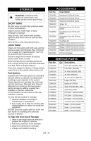
2 1 Lowest Cutting Height 6 3 Highest Cutting 5 Height OF3590 Figure 22 Removing the Mower Deck 1. Remove PTO belt (See Replacing Mower Belts on page 27). 7 4 8 1. Hydro Belt 2. Spring 3. Idler 4. Engine Sheave 5. Right Hand Hydrostat OF1631 6. Left Hand Hydrostat 7. Clutch 8. Clutch Anchor Figure 21 MOWER DECKS Anti-scalp Roller Adjustment The anti-scalp rollers are set at the factory for typical mowing height, but can be adjusted for high or low cutting conditions (Figure 22). Anti-Scalp rollers are intended to prevent lawn scalping, not to control cutting height. For a very high cutting height, set the antiscalp rollers in the lowest position on the bracket. For a very low cutting height, set the antiscalp rollers in the highest position on the bracket. NOTE: There are four anti-scalp rollers on the outside of the mower deck and four antiscalp rollers on the inside of the mower deck. Make sure all anti-scalp rollers are set at the same height. WARNING: AVOID INJURY. Mower lift arms and mower lift pedal could cause severe injury if they are not locked before removing the mower deck. ALWAYS lock mower deck lift before removing the deck. 2. Lock the mower deck in the service position. Push the mower lift pedal forward between cutting height number 4 and number 5 to align the holes in the deck lift shaft and the deck lift cover. Insert the cutting height pin in the holes on the side of the deck lift cover so it passes all the way through the deck lift cover and shaft. IMPORTANT: The mower lift arms are not locked unless the cutting height adjustment pin passes all the way through both the deck lift cover and shaft. NOTE: Support the mower deck on blocks or jack stands before disconnecting link chains from mower lift arms to prevent the deck from falling. 3. Remove link chains from mower lift arms. Note hole location on mower lift arms for replacement. 4. Remove the mower mounting pins connecting the mower mounting arms to the deck. 5. Slide mower deck out from under unit. GB - 29
-
 1
1 -
2
-
3
-
4
-
5
-
6
-
7
-
8
-
9
-
10
-
11
-
12
-
13
-
14
-
15
-
16
-
17
-
18
-
19
-
20
-
21
-
22
-
23
-
 24
24 -
 25
25 -
 26
26 -
 27
27 -
 28
28 -
 29
29 -
 30
30 -
 31
31 -
 32
32 -
 33
33 -
 34
34 -
35
-
36
-
37
-
38
 |
 |
