Ariens Path-Pro 136 Owners Manual - Page 15
Adjust Auger Cable, Replace Belt, Replace Scraper Blade, Auger Control Bar
 |
View all Ariens Path-Pro 136 manuals
Add to My Manuals
Save this manual to your list of manuals |
Page 15 highlights
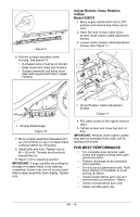
Adjust Auger Cable 1. Move engine switch (Item 16) to OFF position and remove key. Allow unit to cool. 1 3 6 2. Slide plastic sleeve up to auger control bar. 3. Insert Z-hook into appropriate hole in adjustment bracket. When auger control bar is disengaged, there should minor slack in cable and no tension. 4. Engage auger control bar to ensure proper operation. There should be no excessive tension on cable. 5. Lower plastic sleeve. See Figure 7. 2 45 1 2 1. Extension Spring 2. Drive Pulley 3. Idler 4. Idler Bracket 5. Belt Finger 6. Engine Sheave Figure 8 4 3 1. Auger Control Bar 2. Plastic Sleeve 3. Z-hook 4. Adjustment Bracket Figure 7 Replace Belt See MAINTENANCE SCHEDULE on page 17. 1. Move engine switch (Item 16) to OFF position and remove key. Allow unit to cool. 2. Remove five tapping screws from belt cover and remove belt cover. Retain all parts. 3. Disconnect extension sp ring from idler bracket. See Figure 8. 4. Remove belt from drive pulley, idler and engine sheave. 5. Install new belt on engine sheave, idler and drive pulley. Route belt between idler and belt finger on idler bracket. 6. Reinstall extension spring. 7. Reinstall belt cover. Replace Scraper Blade See MAINTENANCE SCHEDULE on page 17. 1. Move engine switch (Item 16) to OFF position and remove key. Allow unit to cool. 2. Tip unit back onto engine guard. 3. Remove nuts, bolts, scraper support and scraper blade. Retain hardware. Discard scraper blade. 4. Check condition of scraper support. Replace if worn or damaged. 5. Insert scraper support into new scraper blade. The D-shaped cutout must be on the left (drive belt side). See Figure 9. EN - 15
-
 1
1 -
2
-
3
-
4
-
5
-
6
-
7
-
8
-
9
-
 10
10 -
 11
11 -
 12
12 -
 13
13 -
 14
14 -
 15
15 -
 16
16 -
 17
17 -
 18
18 -
 19
19 -
 20
20 -
21
-
22
-
23
-
24
 |
 |
