Ariens Pro Track 28 Owners Manual - Page 31
Traction Drive Belt, Replacement, Friction Disc Replacement, Attachment Belts
 |
View all Ariens Pro Track 28 manuals
Add to My Manuals
Save this manual to your list of manuals |
Page 31 highlights
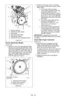
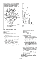
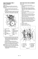
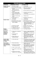
TRACTION DRIVE BELT REPLACEMENT (Figure 37) NOTE: Replacement will be easier with housing and frame tipped apart and bottom cover off. 1. Remove attachment drive belts (see Attachment Drive Belts Replacement on page 30). 2. To gain belt clearance, back out the stop bolt from the frame until the drive plate assembly can swing past it (Figure 38). 1 4 8 2 3 5 9 7 6 OS7221 1. Traction Drive Belt 2. Engine Sheave 3. Attachment Drive Belts 4. Belt Finger 5. Attachment Belts Idler 6. Attachment Pulley 7. Attachment Idler Adjustment Nut 8. Traction Belt Idler 9. Traction Drive Pulley Figure 37 3. Pull idler away from traction drive belt and remove belt from idler pulley, engine sheave and driven pulley (it may be necessary to turn engine pulley using recoil handle). 4. Install new traction drive belt onto attachment pulley and engine sheaves. 5. Pull the drive plate assembly toward the friction disc and tighten the stop bolt. NOTE: Make sure the drive plate assembly return spring remains connected to the frame. 6. Replace attachment drive belts (Attachment Drive Belts Replacement on page 30). FRICTION DISC REPLACEMENT (Figure 38) 1. Place unit into service position. 2. Remove bottom cover by removing six hex bolts. 3. With axle locked, hold one wheel so friction disc will not rotate and remove three cap screws holding friction disc to carrier. 4. Remove both wheels. 5. Remove right and left bearing flanges from frame. 6. Slide hex shaft to the left enough to remove pinion sprocket from hex shaft. 7. Slide hex shaft to the right enough to remove friction disc. 8. Slide new friction disc onto hex shaft. 9. Install pinion sprocket and chain on hex shaft, then replace bearing flanges. 10. Hold wheel so friction disc will not rotate and secure new friction disc to carrier with three hex screws removed in step 2. 11. Replace wheels. 12. Replace bottom cover. 13. Adjust traction drive clutch. 1 2 31 1 4 5 5 8 1 7 6 OS7225 1. Cap Screw 2. Torx Screw 3. Friction Disc 4. Pinion Sprocket 5. Bearing Cap 6. Hex Shaft 7. Drive Plate Assembly 8. Stop Bolt Figure 38 GB - 31
-
 1
1 -
2
-
3
-
4
-
5
-
6
-
7
-
8
-
9
-
10
-
11
-
12
-
13
-
14
-
15
-
16
-
17
-
18
-
19
-
20
-
21
-
22
-
23
-
24
-
25
-
 26
26 -
 27
27 -
 28
28 -
 29
29 -
 30
30 -
 31
31 -
 32
32 -
 33
33 -
 34
34 -
 35
35 -
 36
36 -
37
-
38
-
39
-
40
 |
 |
