Asus AAM6000EV X1 User Manual - Page 8
Rear Panel
 |
View all Asus AAM6000EV X1 manuals
Add to My Manuals
Save this manual to your list of manuals |
Page 8 highlights
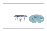
3. Installing the ADSL Modem 3.2 Rear Panel 1 2 3 4 5 6 7 DC+5V/2A Line Phone Console Reset HUB PC USB 10/100-BaseT 1. DC +5V/2A Power Input Jack The provided power adapter converts AC power to DC power for use with this jack. Power supplied through this jack will supply power to the ADSL Modem. 2. Line Connector The RJ-11 connector allows ADSL data communication between the modem and the PSTN through a twisted-pair phone wire. 3. Console Port The 9-pin D-sub serial port supports the RS-232 terminal interface for advanced ADSL modem management. 4. Reset Switch The reset button, when pressed, resets the modem without the need to unplug the power cord. 5. USB Port (optional) The optional USB port allows the modem to be connected to your computer through the USB interface. 6. 10/100-BaseT Ethernet Port The RJ-45 Ethernet port supports 10Base-T networks. (100Base-TX networks will be supported in the near future.) This port allows your PC or Ethernet hub to be connected to the ADSL Modem through a Cat. 5 Ethernet cable. 8
-
 1
1 -
2
-
 3
3 -
 4
4 -
 5
5 -
 6
6 -
 7
7 -
 8
8 -
 9
9 -
 10
10 -
 11
11 -
 12
12 -
 13
13 -
14
-
15
-
16
-
17
-
18
-
19
-
20
-
21
-
22
-
23
-
24
-
25
-
26
-
27
-
28
-
29
-
30
-
31
-
32
 |
 |
