Asus AP130 AP130 User Manual English Edition
Asus AP130 Manual
 |
View all Asus AP130 manuals
Add to My Manuals
Save this manual to your list of manuals |
Asus AP130 manual content summary:
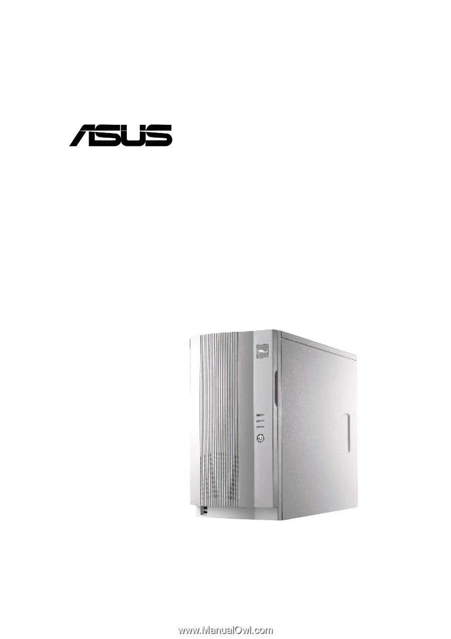
- Asus AP130 | AP130 User Manual English Edition - Page 1
® AP130 Pentium® 4 Pedestal Server User's Manual - Asus AP130 | AP130 User Manual English Edition - Page 2
BY ASUS. ASUS ASSUMES NO RESPONSIBILITY OR LIABILITY FOR ANY ERRORS OR INACCURACIES THAT MAY APPEAR IN THIS MANUAL, INCLUDING THE PRODUCTS AND SOFTWARE DESCRIBED IN IT. Copyright © 2002 ASUSTeK COMPUTER INC. All Rights Reserved. Product Name: Manual Revision: Release Date: ASUS AP130 1.00 - Asus AP130 | AP130 User Manual English Edition - Page 3
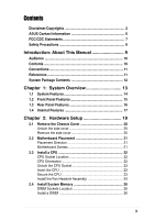
Contents Disclaimer/Copyrights 2 ASUS Contact Information 6 FCC/CDC Statements 7 Safety Precautions 8 Introduction: About This Manual 9 Audience 10 Contents 10 Conventions 11 References 11 System Package Contents 12 Chapter 1: System Overview 13 1.1 System Features 14 1.2 Front Panel - Asus AP130 | AP130 User Manual English Edition - Page 4
Check Power Status 32 Appendix A: Power Supply 33 A.1 General Description 34 A.2 Specifications 35 Input Characteristics 35 Output Characteristics 35 Over-Voltage Protection (OVP 35 Appendix B: Troubleshooting 47 B.1 Simple Fixes 48 4 - Asus AP130 | AP130 User Manual English Edition - Page 5
Center, Building 2, Newark, CA 94560, USA +1-510-608-4555 [email protected] Technical Support Support Fax: Notebook (Tel): Web Site: Support Email: +1-510-608-4555 1-877-918-ASUS (2787) www.asus.com [email protected] ASUS COMPUTER GmbH (Europe) Address: General Fax: General Email: Harkortstr. 25 - Asus AP130 | AP130 User Manual English Edition - Page 6
. This equipment generates, uses and can radiate radio frequency energy and, if not installed and used in accordance with manufacturer's instructions, may cause harmful interference to radio communications. However, there is no guarantee that interference will not occur in a particular installation - Asus AP130 | AP130 User Manual English Edition - Page 7
supply is broken, do not try to fix it by yourself. Contact a qualified service technician or your dealer. CAUTION This product is equipped with a three-wire power engineers. • Before operating the server, carefully read all the manuals included with the server package. • Before using the server, - Asus AP130 | AP130 User Manual English Edition - Page 8
8 - Asus AP130 | AP130 User Manual English Edition - Page 9
About This Manual Introduction "About This Manual" introduces the contents of this document. This part includes the target audience, chapter description, and conventions used. It also lists other sources of information that are not contained in this manual. ASUS AP130 Pedestal Server 9 - Asus AP130 | AP130 User Manual English Edition - Page 10
Appendix B: Troubleshooting This appendix lists the common problems that you may encounter while using the AP130 server. It lists the possible causes of the problems and offers solutions. You may refer to this part and try to solve simple problems before calling customer support. 10 Introduction - Asus AP130 | AP130 User Manual English Edition - Page 11
Information on page 5. 3. Optional Documentation Your product package may include optional documentation such as a CD-ROM manual, warranty flyers, and others that may have been added by your dealer. NOTE: These documents are not part of the standard server package. ASUS AP130 Pedestal Server 11 - Asus AP130 | AP130 User Manual English Edition - Page 12
3) 200W ATX power supply 4) 52X CD-ROM drive 5) 1.44MB floppy disk drive 6) AGP 4X card (optional) 7) Support CD that includes drivers, utilities, and ASUS Server Web-based Management (ASWM) 8) User's manuals (for system and motherboard) If any of the above items is missing, contact your dealer. 12 - Asus AP130 | AP130 User Manual English Edition - Page 13
Chapter 1 This chapter describes the general features of the AP130 server. It includes sections on front panel, rear panel, and internal features of the server. System Overview ASUS AP130 Pedestal Server 13 - Asus AP130 | AP130 User Manual English Edition - Page 14
1.1 System Features The ASUS AP130 Server is a stylish tower chassis that accommodates the ASUS P4B-MX motherboard. The server is powered by Intel® Pentium® 4 478/Northwood processor, and supports the latest I/O, audio, and video technologies through the chipsets embedded on the motherboard. - Asus AP130 | AP130 User Manual English Edition - Page 15
Panel Door Keylock CD-ROM Drive 5.25-inch Drive Bay Floppy Disk Drive Power Switch Power LED HD Access LED Message LED Front USB Ports ASUS AP130 Pedestal Server 15 - Asus AP130 | AP130 User Manual English Edition - Page 16
1.3 Rear Panel Features The AP130 rear panel includes the external I/O ports. The following picture shows the cable connectors and the devices that you connect to the ports. PS/2 KB Serial - Asus AP130 | AP130 User Manual English Edition - Page 17
1.4 Internal Features The standard components inside the AP130 server include the motherboard, power supply, floppy and CD-ROM drives, and cables. The Drive Bay 4. Floppy Disk Drive 5. 3.5-inch Internal Drive Bays 6. P4B-MX Motherboard 7. AGP 4X Card (optional) ASUS AP130 Pedestal Server 17 - Asus AP130 | AP130 User Manual English Edition - Page 18
18 Chapter 1: System Overview - Asus AP130 | AP130 User Manual English Edition - Page 19
Chapter 2 This chapter describes the hardware setup procedures that you have to perform when installing system components. Hardware Setup ASUS AP130 Pedestal Server 19 - Asus AP130 | AP130 User Manual English Edition - Page 20
2.1 Remove the Chassis Cover Unlock the side cover Two thumbscrews secure the removable side panel cover. Turn these screws counter-clockwise to release the cover. The screws are attached to the cover. Do pull out the screws. Remove the side cover Slide the cover for about an inch toward the rear - Asus AP130 | AP130 User Manual English Edition - Page 21
other internal components of the AP130 server are already installed as indicated in section "1.4 Internal Features". Refer to the motherboard user's manual for detailed technical information chassis. Do not overtighten the screws. Doing so may damage the motherboard. ASUS AP130 Pedestal Server 21 - Asus AP130 | AP130 User Manual English Edition - Page 22
2.3 Install a CPU The 478-pin Zero Insertion Force (ZIF) socket on the P4B-MX motherboard supports an Intel Pentium 4 processor. This section tells you how to install a CPU. Refer to the motherboard user guide for more information. CPU Socket Location The CPU socket is located beside the rear panel - Asus AP130 | AP130 User Manual English Edition - Page 23
tab to indicate that it is locked. CAUTION Incorrect installation of the CPU into the socket may bend the pins and severely damage the CPU! ASUS AP130 Pedestal Server 23 - Asus AP130 | AP130 User Manual English Edition - Page 24
Install the Fan Heatsink Assembly 1. Align and snap the hooks of a retention bracket into the holes of the retention module base. Make sure that the arrow on the bracket points inward. 2. Follow step 1 to install the other bracket. 3. When attached to the module base, flip the brackets sideways to - Asus AP130 | AP130 User Manual English Edition - Page 25
that you purchased may not look exactly the same as shown. Refer to the documentation that came with the fan heatsink assembly for more information. ASUS AP130 Pedestal Server 25 - Asus AP130 | AP130 User Manual English Edition - Page 26
2.4 Install System Memory DIMM Sockets Location The motherboard has three Dual Inline Memory Module (DIMM) sockets that support 3.3V SDRAM modules in 32, 64, 128, 256, 512MB, or 1GB densities for up to 3GB system memory. DIMM sockets Install a DIMM 1. Unlock a DIMM socket - Asus AP130 | AP130 User Manual English Edition - Page 27
cage out of the chassis. HDD Metal Cage 2. Press the retaining clip to release the cage. 3. Lift the cage out of the chassis. Retaining clip ASUS AP130 Pedestal Server 27 - Asus AP130 | AP130 User Manual English Edition - Page 28
Install the HDD 1. Insert the HDD into the cage (label side up) until the holes on the HDD align with the holes on the cage. 2. Secure the HDD with four screws (two on each side). 3. Replace the cage into the chassis. Connect the Cables 1. Connect one end of the IDE cable to the IDE connector at - Asus AP130 | AP130 User Manual English Edition - Page 29
the chassis edge. 2. Slide the cover toward the front panel until it fits in place. 3. Turn the thumbscrews to secure the cover to the chassis. ASUS AP130 Pedestal Server 29 - Asus AP130 | AP130 User Manual English Edition - Page 30
30 Chapter 2: Hardware Setup - Asus AP130 | AP130 User Manual English Edition - Page 31
Chapter 3 This chapter tells how to get started with the AP130 server. Powering up the server basically includes connecting the cables and turning power on. Powering Up ASUS AP130 Pedestal Server 31 - Asus AP130 | AP130 User Manual English Edition - Page 32
3.1 Getting Started Make sure that you have completed the basic system installations in Chapter 2, then follow these steps to start up the server. Connect a Monitor Connect a monitor by plugging hte monitor cable to the video port (blue port) on the server rear panel. Video Port Connect the Power - Asus AP130 | AP130 User Manual English Edition - Page 33
Appendix A This appendix gives information on the 200W switching power supply that comes with the AP130 server. Power Supply ASUS AP130 Pedestal Server 33 - Asus AP130 | AP130 User Manual English Edition - Page 34
A.1 General Description The server comes with a 200W ATX power supply with universal AC input that includes PFC and ATX-compliant output cables and connectors. The power supply has an internal cooling fan. The power supply has seven plugs labeled PS1, P2, P3, P4, P5, P6, and P7. The picture below - Asus AP130 | AP130 User Manual English Edition - Page 35
for shorting +5V, +12V, -12V, or +3.3V. By shorting +5Vsb, the power supply can latch down or automatically recover when the fault condition is removed. ASUS AP130 Pedestal Server 35 - Asus AP130 | AP130 User Manual English Edition - Page 36
36 Appendix A: Power Supply - Asus AP130 | AP130 User Manual English Edition - Page 37
appendix lists the common problems that you may encounter while using the AP130 server. It lists the possible causes of the problems and offers solutions. You may refer to this part and try to solve simple problems before calling customer support. Troubleshooting ASUS AP130 Pedestal Server 37 - Asus AP130 | AP130 User Manual English Edition - Page 38
on the system or the components. These problems only requires simple troubleshooting actions that you can perform by yourself. Problem Action The power LED on the server and the system supports. 2. Make sure that the DIMMs are properly installed on the sockets. 38 Appendix B: Troubleshooting - Asus AP130 | AP130 User Manual English Edition - Page 39
not available Install the utility drivers from the support CD that came with the package. 1. Make sure the network cable is connector the RJ-45 port on the rear panel. 2. Make sure that you have installed the network drivers from the motherboard support CD. ASUS AP130 Pedestal Server 39 - Asus AP130 | AP130 User Manual English Edition - Page 40
40 Appendix B: Troubleshooting
-
 1
1 -
 2
2 -
 3
3 -
 4
4 -
 5
5 -
 6
6 -
 7
7 -
8
-
9
-
10
-
11
-
12
-
13
-
14
-
15
-
16
-
17
-
18
-
19
-
20
-
21
-
22
-
23
-
24
-
25
-
26
-
27
-
28
-
29
-
30
-
31
-
32
-
33
-
34
-
35
-
36
-
37
-
38
-
39
-
40
 |
 |
Pentium
®
4 Pedestal Server
®
AP130
User’s Manual