Asus AP130 AP130 User Manual English Edition - Page 28
Install the HDD, Connect the Cables
 |
View all Asus AP130 manuals
Add to My Manuals
Save this manual to your list of manuals |
Page 28 highlights
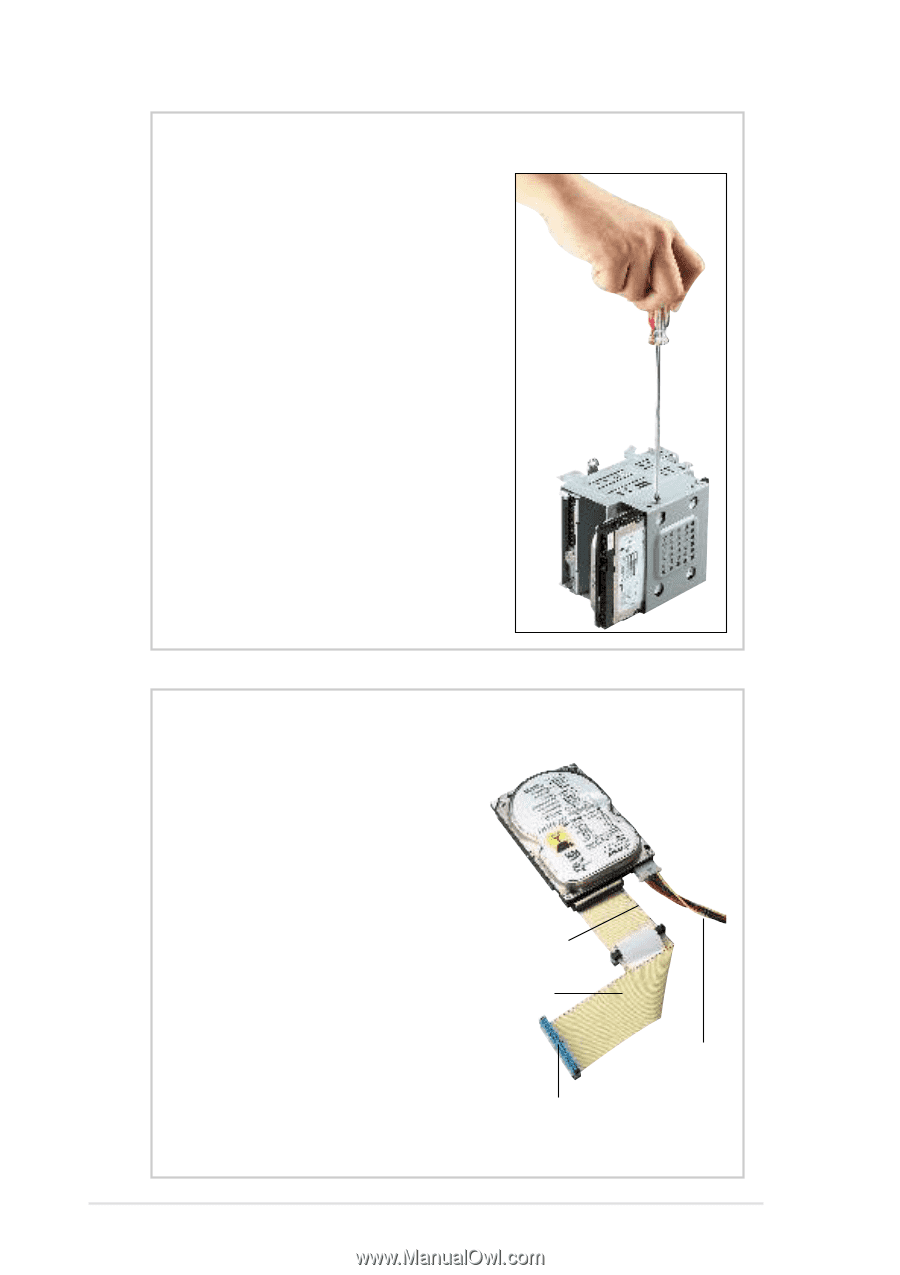
Install the HDD 1. Insert the HDD into the cage (label side up) until the holes on the HDD align with the holes on the cage. 2. Secure the HDD with four screws (two on each side). 3. Replace the cage into the chassis. Connect the Cables 1. Connect one end of the IDE cable to the IDE connector at the back of the drive, matching the red stripe on the cable with Pin 1 on the IDE connector. 2. Connect a power cable (plug marked P5) to the power connector at the back of the drive. Red Stripe to Pin 1 IDE Cable 3. Connect the other end of the IDE cable to the primary IDE connector (blue connector) on the motherboard. Power Cable (P5) To primary IDE connector on the motherboard 28 Chapter 2: Hardware Setup
-
 1
1 -
2
-
3
-
4
-
5
-
6
-
7
-
8
-
9
-
10
-
11
-
12
-
13
-
14
-
15
-
16
-
17
-
18
-
19
-
20
-
21
-
22
-
 23
23 -
 24
24 -
 25
25 -
 26
26 -
 27
27 -
 28
28 -
 29
29 -
 30
30 -
 31
31 -
 32
32 -
 33
33 -
34
-
35
-
36
-
37
-
38
-
39
-
40
 |
 |
28
Chapter 2:
Hardware Setup
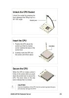
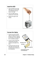
Install the HDD
1.
Insert the HDD into the cage
(label side up) until the holes
on the HDD align with the
holes on the cage.
2.
Secure the HDD with four
screws (two on each side).
3.
Replace the cage into the
chassis.
Connect the Cables
1.
Connect one end of the IDE
cable to the IDE connector at
the back of the drive, matching
the red stripe on the cable with
Pin 1 on the IDE connector.
2.
Connect a power cable (plug
marked P5) to the power
connector at the back of the
drive.
3.
Connect the other end of the
IDE cable to the primary IDE
connector (blue connector) on
the motherboard.
IDE Cable
Red Stripe to Pin 1
Power Cable (P5)
To primary IDE connector
on the motherboard