Asus AT4NM10-I User Manual - Page 11
Motherboard overview - atom d410
 |
View all Asus AT4NM10-I manuals
Add to My Manuals
Save this manual to your list of manuals |
Page 11 highlights
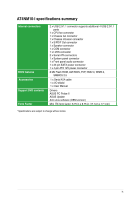
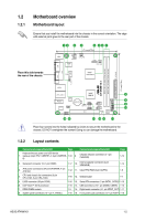
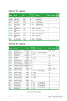
1.2 1.2.1 Motherboard overview Motherboard layout Ensure that you install the motherboard into the chassis in the correct orientation. The edge with external ports goes to the rear part of the chassis. Place this side towards the rear of the chassis. Atom D410 AT4NM10-I Place four screws into the holes indicated by circles to secure the motherboard to the chassis. DO NOT overtighten the screws! Doing so can damage the motherboard. 1.2.2 Layout contents Connectors/Jumpers/Slots/LED Page Connectors/Jumpers/Slots/LED Page Keyboard/mouse power and USB device 1. wake-up (3-pin PS2_USBPW1-4, 3-pin USBPW5- 1-10 9. 8) Chassis intrusion connector (4-1 pin CHASSIS) 1-14 2. Serial port connector (10-1 pin COM2) 1-17 10. Internal speaker connector (4-pin SPEAKER) 1-14 3. ATX power connectors (24-pin EATXPWR, 4-pin ATX12V) 1-12 11. Clear RTC RAM (3-pin CLRTC) 1-9 4. CPU and chassis fan connectors (3-pin CPU_FAN, 3-pin CHA_FAN) 1-15 12. Onboard LED 1-1 5. LVDS connector (30-pin CON1) 1-16 13. Serial ATA connectors (7-pin SATA1, SATA2) 1-13 6. Intel® Atom™ D410 processor 1-15 14. USB connectors (10-1 pin USB56, USB78) 1-13 7. DDR2 DIMM sockets 1-3 15. Digital audio connector (4-1 pin SPDIF_OUT) 1-17 8. System panel connector (10-1 pin F_PANEL) 1-16 16. Front panel audio connector (10-1 pin AAFP) 1-15 ASUS AT4NM10-I 1-2
-
 1
1 -
2
-
3
-
4
-
5
-
 6
6 -
 7
7 -
 8
8 -
 9
9 -
 10
10 -
 11
11 -
 12
12 -
 13
13 -
 14
14 -
 15
15 -
 16
16 -
17
-
18
-
19
-
20
-
21
-
22
-
23
-
24
-
25
-
26
-
27
-
28
-
29
-
30
-
31
-
32
-
33
-
34
-
35
-
36
-
37
-
38
-
39
-
40
-
41
-
42
-
43
-
44
 |
 |
