Asus B150M-A User Guide
Asus B150M-A Manual
 |
View all Asus B150M-A manuals
Add to My Manuals
Save this manual to your list of manuals |
Asus B150M-A manual content summary:
- Asus B150M-A | User Guide - Page 1
B150M-A Motherboard - Asus B150M-A | User Guide - Page 2
service will not be extended if: (1) the product is repaired, modified or altered, unless such repair, modification of alteration is authorized in writing by ASUS; or (2) the serial number of the product is defaced or missing. ASUS PROVIDES THIS MANUAL from http://support.asus.com/download problems - Asus B150M-A | User Guide - Page 3
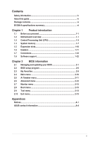
Before you proceed 1-1 1.2 Motherboard overview 1-1 1.3 Central Processing Unit (CPU 1-3 1.4 System memory 1-7 1.5 Expansion slots 1-10 1.6 Headers 1-11 1.7 Connectors 1-12 1.8 Software support 1-22 Chapter 2 BIOS information 2.1 Managing and updating your BIOS 2-1 2.2 BIOS setup program - Asus B150M-A | User Guide - Page 4
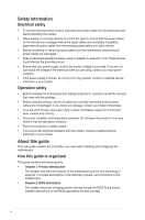
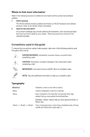
. • If you encounter technical problems with the product, contact a qualified service technician or your retailer. About this guide This user guide contains the information you need when installing and configuring the motherboard. How this guide is organized This guide contains the following parts - Asus B150M-A | User Guide - Page 5
to the following sources for additional information and for product and software updates. 1. ASUS websites The ASUS website provides updated information on ASUS hardware and software products. Refer to the ASUS contact information. 2. Optional documentation Your product package may include optional - Asus B150M-A | User Guide - Page 6
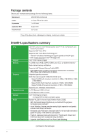
items. Motherboard ASUS B150M-A motherboard Cables 2 x Serial ATA 6.0 Gb/s cables Accessories Application DVD 1 x I/O Shield Support DVD Documentation User Guide If any of the above items is damaged or missing, contact your retailer. B150M-A specifications summary CPU Chipset Memory - Asus B150M-A | User Guide - Page 7
B150M-A specifications summary LAN USB ASUS special features Realtek® RTL8111H Gigabit LAN controller Intel® B150 Express Chipset - supports ASUS USB 3.0 Boost - 1 x 5Gb/s USB Type C port supports 3A power output (at back panel) - 4 x USB 3.0/2.0 ports (2 ports at mid-board; 2 ports at back panel, - Asus B150M-A | User Guide - Page 8
B150M-A specifications summary ASUS special features ASUS quiet thermal solution Rear panel I/O ports Internal connectors EZ DIY Push Notice - Monitor your PC status with smart devices in real time UEFI BIOS EZ Mode - featuring friendly graphics user interface - ASUS CrashFree BIOS 3 - ASUS EZ - Asus B150M-A | User Guide - Page 9
, WOR by PME, PXE Drivers ASUS utilities EZ Update Anti-virus software (OEM version) Windows® 10 (64-bit) / Windows® 8.1 (64-bit) / Windows® 7 (64-bit/32-bit) * Please refer to ASUS official website and download Windows® 7 Installation Guide and EZ Installer to install Windows® 7. mATX form factor - Asus B150M-A | User Guide - Page 10
x - Asus B150M-A | User Guide - Page 11
the rear part of the chassis as indicated in the image. 1.2.2 Screw holes Place six screws into the holes indicated by circles to secure the motherboard to the chassis. Do not overtighten the screws! Doing so can damage the motherboard. ASUS B150M-A 1-1 - Asus B150M-A | User Guide - Page 12
towards the rear of the chassis B150M-A 1.2.3 Motherboard layout 12 3 20.1cm(7.9in) 2 4 KBMS HDMI ASM 1442K ATX12V CPU_FAN DIGI +VRM CHA_FAN2 DDR4 DIMM_A1 (64bit, 288-pin module) DDR4 DIMM_A1 (64bit, 288-pin module) DDR4 DIMM_A1 (64bit, 288-pin module) DDR4 DIMM_A1 (64bit, 288-pin module - Asus B150M-A | User Guide - Page 13
ATX12V) 2. CPU, chassis fan connectors (4-pin CPU_FAN, 4-pin CHA_FAN1~2) 3. Intel® LGA1151 CPU socket 4. DDR4 DIMM slots 5. 1-21 1-16 1-16 1-21 1-18 1-15 1-18 1.3 Central Processing Unit (CPU) This motherboard comes with a surface mount LGA1151 socket designed for the 6th Generation Intel® Core™ i7 - Asus B150M-A | User Guide - Page 14
Keep the cap after installing the motherboard. ASUS will process Return Merchandise Authorization (RMA) requests only if the motherboard comes with the cap on the LGA1151 socket. • The product warranty does not cover damage to the socket contacts resulting from incorrect CPU installation/removal, or - Asus B150M-A | User Guide - Page 15
4 C 5 A B 1.3.2 CPU heatsink and fan assembly installation Apply the Thermal Interface Material to the CPU heatsink and CPU before you install the heatsink and fan if necessary. ASUS B150M-A 1-5 - Asus B150M-A | User Guide - Page 16
To install the CPU heatsink and fan assembly 1 A B 2 B A 3 4 To uninstall the CPU heatsink and fan assembly 1 2 A B B A 1-6 Chapter 1: Product introduction - Asus B150M-A | User Guide - Page 17
install a DDR, DDR2, or DDR3 memory module to the DDR4 slot. According to Intel® CPU spec, DIMM voltage below 1.35 V is recommended to protect the CPU. DIMM_A1 DIMM_A2 DIMM_B1 DIMM_B2 Channel B150M-A Channel A Channel B B150M-A 288-pin DDR4 DIMM sockets Sockets DIMM_A1 & DIMM_A2 DIMM_B1 & DIMM_B2 - Asus B150M-A | User Guide - Page 18
CPU spec, DIMM voltage below 1.35V is recommended to protect the CPU. • Due to the memory address limitation on 32-bit Windows® OS, when you install 4GB or more memory on the motherboard to support a full memory load (4 DIMMs) or overclocking condition. Visit the ASUS website at www.asus.com for - Asus B150M-A | User Guide - Page 19
1.4.3 1 Installing a DIMM 2 3 To remove a DIMM B A ASUS B150M-A 1-9 - Asus B150M-A | User Guide - Page 20
slots, ensure that the drivers support "Share IRQ" or that the cards do not need IRQ assignments. Otherwise, conflicts will arise between the two PCI groups, making the system unstable and the card inoperable. 1.5.3 PCI Express 3.0/2.0 x1 slots This motherboard supports PCI Express x1 network cards - Asus B150M-A | User Guide - Page 21
IRQ assignments for this motherboard PCIEx16 PCIEx1_1 PCIEx1_2 Realtek 8111H LAN overclocking. For system failure due to overclocking, use the CPU Parameter Recall (C.P.R.) feature. Shut down and reboot the system, then the BIOS automatically resets parameter settings to default values. ASUS B150M - Asus B150M-A | User Guide - Page 22
Remove the jumper caps only when you intend to use the chassis intrusion detection feature. +5VSB_MB Chassis Signal GND CHASSIS B150M-A B150M-A Chassis intrusion connector 1.7 1.7.1 1 Connectors Rear panel connectors 2 3 45 12 11 10 9 8 7 6 1. PS/2 mouse port (green). This port is for - Asus B150M-A | User Guide - Page 23
Out Front Speaker Out Bass/Center Side Speaker Out To configure a 7.1-channel audio output: Use a chassis with HD audio module in the front panel to support a 7.1-channel audio output. 7. USB 2.0 ports. These 4-pin Universal Serial Bus (USB) ports are for USB 2.0/1.1 devices - Asus B150M-A | User Guide - Page 24
ports are controlled by the xHCI controller. Some legacy USB devices must update their firmware for better compatibility. 9. USB 5Gb/s Type C port. , two displays under BIOS, and one display under DOS. • Intel® display architecture design supports the following maximum supported pixel clocks (Pixel - Asus B150M-A | User Guide - Page 25
forget to connect the fan cables to the fan connectors. Insufficient air flow inside the system may damage the motherboard components. These are not jumpers! Do not place jumper caps on the fan connectors! The CPU_FAN connector supports a CPU fan of maximum 1A (12 W) fan power. ASUS B150M-A 1-15 - Asus B150M-A | User Guide - Page 26
chassis. These USB connectors comply with USB 2.0 specifications and supports up to 480Mbps connection speed. USB+5V USB_P9USB_P9+ GND B150M-A USB1112 PIN 1 USB+5V USB_P12USB_P12+ GND B150M-A USB2.0 connectors Never connect a 1394 cable to the USB connector. Doing so will damage the motherboard - Asus B150M-A | User Guide - Page 27
is inadequate. • If you are uncertain about the minimum power supply requirement for your system, refer to the Recommended Power Supply Wattage Calculator at http://support.asus. com/PowerSupplyCalculator/PSCalculator.aspx?SLanguage=en-us for details. ASUS B150M-A 1-17 - Asus B150M-A | User Guide - Page 28
audio I/O module that supports either HD Audio or PORT2 L B150M-A HD-audio-compliant pin definition B150M-A Front panel motherboard's high-definition audio capability. • If you want to connect a high-definition front panel audio module to this connector, set the Front Panel Type item in the BIOS - Asus B150M-A | User Guide - Page 29
) This connector supports several chassis-mounted functions. F_PANEL +PWR LED PWR BTN PWR_LED+ PWR_LEDPWR GND HDD_LED+ HDD_LED- Ground HWRST# (NC) B150M-A PIN 1 +HDD_LED RESET B150M-A System panel connector reset button for system reboot without turning off the system power. ASUS B150M-A 1-19 - Asus B150M-A | User Guide - Page 30
RSATA_RXN2 GND RSATA_TXN2 RSATA_TXP2 GND B150M-A SATA 6.0Gb/s connectors • You must install Windows. XP Service Pack 3 or later version before using Serial ATA hard disk drives. • When using hot-plug and NCQ, set the SATA Mode Selection item in the BIOS to - Asus B150M-A | User Guide - Page 31
C_PCICLK_TPM +3V +3V B150M-A TPM connector The TPM module is purchased separately. 12. LPT connector (26-1 pin LPT) The LPT (Line Printing Terminal) connector supports devices such as a #_R O_LPT_BUSY_R O_LPT_PE_R O_LPT_SLCT_R B150M-A LPT PIN 1 B150M-A Parallel Port connector ASUS B150M-A 1-21 - Asus B150M-A | User Guide - Page 32
. Visit the ASUS website at www.asus.com for updates. To run the Support DVD Place the Support DVD into the optical drive. If Autorun is enabled in your computer, the DVD automatically displays the lists of the unique features of your ASUS motherboard. Click the Driver, Utilities, Manual, or Special - Asus B150M-A | User Guide - Page 33
to automatically update your motherboard's driver, software and firmware Click to find and select the BIOS from file Click to select a boot logo Click to update the BIOS EZ Update requires an Internet connection either through a network or an ISP (Internet Service Provider). ASUS B150M-A 2-1 - Asus B150M-A | User Guide - Page 34
the BIOS update process. Via the Internet a) Select by Internet. b) Press the Left/Right arrow keys to select an Internet connection method, and then press . c) Follow the onscreen instructions to complete the update. 3. Reboot the system when the update process is done. • ASUS EZ Flash - Asus B150M-A | User Guide - Page 35
failure! 2.1.4 ASUS BIOS Updater ASUS BIOS Updater allows you to update the BIOS in DOS environment. The screen captures used in this section are for reference only and may not be exactly the same as actually shown on your computer screen. Before updating BIOS • Prepare the motherboard support DVD - Asus B150M-A | User Guide - Page 36
in DOS: 1. Insert the USB flash drive with the latest BIOS file and BIOS Updater to the USB port. 2. Boot your computer then press to launch the select boot device screen. 3. When the select boot device screen appears, insert the Support DVD into the optical drive then select the optical drive - Asus B150M-A | User Guide - Page 37
shut down or reset the system while updating the BIOS to prevent system boot failaure. Ensure to load the BIOS default settings to ensure system compatibility and stability. Select the Load Optimized Defaults item under the Exit BIOS menu. See section 2.10 Exit Menu for details. ASUS B150M-A 2-5 - Asus B150M-A | User Guide - Page 38
what you see on your screen. • Visit the ASUS website at www.asus.com to download the latest BIOS file for this motherboard. • Ensure that a USB mouse is connected to your motherboard if you want to use the mouse to control the BIOS setup program. • If the system becomes unstable after changing - Asus B150M-A | User Guide - Page 39
Boot menu for details. Displays the CPU/motherboard temperature, CPU voltage output, CPU/chassis fan speed, and SATA information Selects the display language of the BIOS setup program Displays the system properties of vary depending on the devices you installed to the system. ASUS B150M-A 2-7 - Asus B150M-A | User Guide - Page 40
experienced end-users to configure the BIOS settings. The figure below shows an to EZ Mode Searches FAQ Displays the CPU/motherboard temperature, CPU and memory voltage output Menu bar The menu basic system configuration For changing the overclocking settings For changing the advanced system - Asus B150M-A | User Guide - Page 41
Favorites To add BIOS items: 1. Press on your keyboard or click Setup Tree Map screen. from the BIOS screen to open 2. On the Setup Tree Map screen, select the BIOS items that you want to save in MyFavorites screen. Main menu panel Submenu panel Selected shortcut items ASUS B150M-A 2-9 - Asus B150M-A | User Guide - Page 42
key to close Setup Tree Map screen. 5. Go to My Favorites menu to view the saved BIOS items. 2.4 Main menu The Main menu screen appears when you enter the Advanced Mode of the BIOS Setup program. The Main menu provides you an overview of the basic system information, and allows you - Asus B150M-A | User Guide - Page 43
of the Ai Tweaker menu items. Incorrect field values can cause the system to malfunction. The configuration options for this section vary depending on the CPU and DIMM model you installed on the motherboard. Scroll down to display other BIOS items. ASUS B150M-A 2-11 - Asus B150M-A | User Guide - Page 44
2.6 Advanced menu The Advanced menu items allow you to change the settings for the CPU and other system devices. Be cautious when changing the settings of the Advanced menu items and allows you to change the fan settings. Scroll down to display the other BIOS items. 2-12 Chapter 2: Getting started - Asus B150M-A | User Guide - Page 45
items allow you to change the system boot options. Scroll down to display the other BIOS items. 2.9 Tool menu The Tool menu items allow you to configure options for special to load the optimal default values for the BIOS items, and save or discard your changes to the BIOS items. ASUS B150M-A 2-13 - Asus B150M-A | User Guide - Page 46
2-14 Chapter 2: Getting started - Asus B150M-A | User Guide - Page 47
radio frequency energy and, if not installed and used in accordance with manufacturer's instructions, may cause harmful interference to radio communications. However, there is no guarantee that y compris celles susceptibles de provoquer un fonctionnement non souhaité de l'appareil. ASUS B150M-A A-1 - Asus B150M-A | User Guide - Page 48
use the equipment according to the instruction manual. KC: Korea Warning Statement REACH at ASUS REACH website at http://csr.asus.com/english/REACH.htm. DO NOT throw the motherboard in be placed in municipal waste. ASUS Recycling/Takeback Services ASUS recycling and takeback programs come from - Asus B150M-A | User Guide - Page 49
alle direttive CE. Per maggiori informazioni fate riferimento alla dichiarazione di conformità CE. ASUS AsusTek Inc CE CE Hrvatski AsusTek Inc. ovim izjavljuje da je ovaj uređaj propisima Direktiva EK. Za više informacija molimo pogledajte Deklaraciju o usklađenosti EK. ASUS B150M-A A-3 - Asus B150M-A | User Guide - Page 50
USA Telephone +1-510-739-3777 Fax +1-510-608-4555 Web site http://www.asus.com/us/ Technical Support Support fax General support Online support +1-812-284-0883 +1-812-282-2787 http://www.service.asus.com/ ASUS COMPUTER GmbH (Germany and Austria) Address Harkort Str. 21-23, D-40880 - Asus B150M-A | User Guide - Page 51
: Product name : Model name : ASUSTeK COMPUTER INC. 4F, No. 150, LI-TE Rd., PEITOU, TAIPEI 112, TAIWAN ASUS COMPUTER GmbH HARKORT STR. 21-23, 40880 RATINGEN GERMANY Motherboard B150M-A conform with the essential requirements of the following directives: 2004/108/EC-EMC Directive EN 55022:2010+AC
-
 1
1 -
 2
2 -
 3
3 -
 4
4 -
 5
5 -
 6
6 -
 7
7 -
8
-
9
-
10
-
11
-
12
-
13
-
14
-
15
-
16
-
17
-
18
-
19
-
20
-
21
-
22
-
23
-
24
-
25
-
26
-
27
-
28
-
29
-
30
-
31
-
32
-
33
-
34
-
35
-
36
-
37
-
38
-
39
-
40
-
41
-
42
-
43
-
44
-
45
-
46
-
47
-
48
-
49
-
50
-
51
 |
 |

Motherboard
B150M-A