Asus C8HM70-I HDMI C8HM70-I User's Manual - Page 13
Motherboard layout, Layout contents - vga to hdmi
 |
View all Asus C8HM70-I HDMI manuals
Add to My Manuals
Save this manual to your list of manuals |
Page 13 highlights
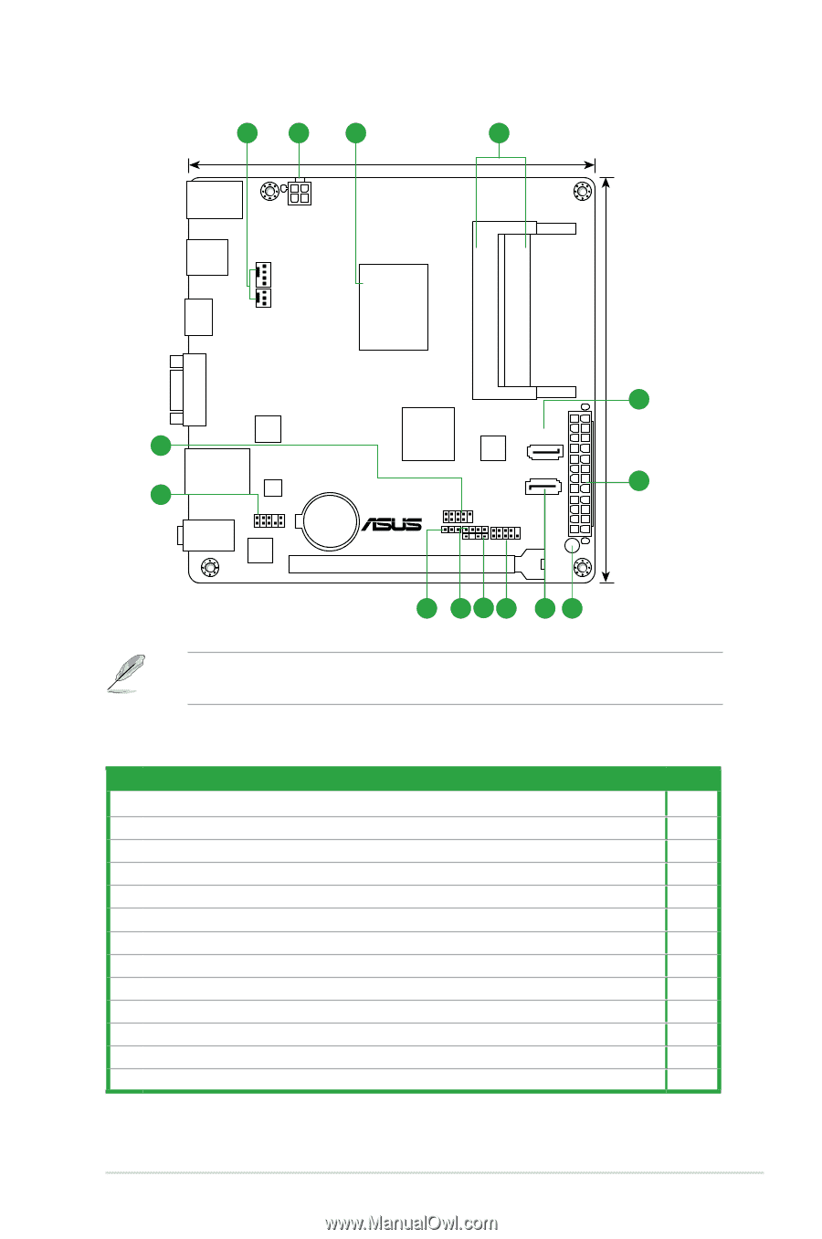
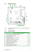
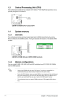
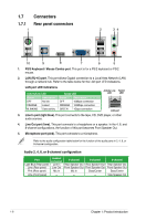
1.2.3 Motherboard layout 1 2 3 4 17.0cm(6.7in) KB_USB910 ATX12V USB3_12 CHA_FAN HDMI CPU_FAN Intel® Celeron847 DDR3 DIMM_B1 (64bit, 204-pin module) DDR3 DIMM_A1 (64bit, 204-pin module) 17.0cm(6.7in) VGA 5 Super I/O 13 Intel® HM70 64Mb BIOS SATA6G_1 LAN_USB34 12 RTL 8111F SATA3G_1 2 USB1112 EATXPWR AUDIO AAFP ALC 887 Lithium Cell CMOS Power CLRTC C8HM70-I/HDMI PCIEX16_1 F_PANEL SPEAKER CHASSIS SB_PWR 11 10 9 8 7 6 Following Intel's specification, USB 2.0 ports 5 ~ 8 are disabled on the motherboards with Intel® HM70 chipset. 1.2.4 Layout contents Connectors/Jumpers/Slots/LED 1. CPU and chassis fan connectors (3-pin CPU_FAN and 4-pin CHA_FAN) 2. ATX power connectors (24-pin EATXPWR, 4-pin ATX12V) 3. Intel® Celeron847 (BGA1023) processor 4. DDR3 SO-DIMM sockets 5. Serial ATA 6.0Gb/s connectors (7-pin SATA6G [gray]) 6. Standby power LED (SB_PWR) 7. Serial ATA 3.0Gb/s connectors (7-pin SATA3G [blue]) 8. System panel connector (10-1 pin PANEL) 9. Chassis intrusion connector (4-1 pin CHASSIS) 10. Speaker connector (4-pin SPEAKER) 11. Clear RTC RAM (3-pin CLRTC) 12. Front panel audio connector (10-1 pin AAFP) 13. USB 2.0 connectors (10-1 pin USB1112) Page 1-12 1-11 1-4 1-4 1-13 1-1 1-13 1-14 1-11 1-14 1-7 1-10 1-12 ASUS C8HM70-I Series 1-3
-
 1
1 -
2
-
3
-
4
-
5
-
6
-
7
-
 8
8 -
 9
9 -
 10
10 -
 11
11 -
 12
12 -
 13
13 -
 14
14 -
 15
15 -
 16
16 -
 17
17 -
 18
18 -
19
-
20
-
21
-
22
-
23
-
24
-
25
-
26
-
27
-
28
-
29
-
30
-
31
-
32
-
33
-
34
-
35
-
36
-
37
-
38
-
39
-
40
-
41
-
42
-
43
-
44
-
45
-
46
-
47
-
48
-
49
-
50
-
51
-
52
-
53
-
54
-
55
-
56
-
57
-
58
-
59
-
60
-
61
-
62
 |
 |