Asus CUVL-VM CUVL-VM User Manual - Page 15
ASUS CUVL-VM User's Manual, Motherboard Settings, Expansion Slots/Sockets, Connectors
 |
View all Asus CUVL-VM manuals
Add to My Manuals
Save this manual to your list of manuals |
Page 15 highlights
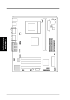
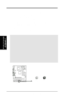
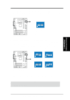
3. HARDWARE SETUP 3.2 Layout Contents Motherboard Settings 1) SW1 2) CLR_CMOS Expansion Slots/Sockets 1) DIMM 1/2 2) Socket 370 3) PCI 1/2/3 Connectors 1) PS2KBMS 2) PS2KBMS 3) USB 4) PRINTER 5) COM1 6) VGA 7) GAME_AUDIO 8) IDELED 9) FLOPPY 10) PRIMARY IDE SECONDARY IDE 11) WOL_CON 12) WOR 13) CPU/PWR/CHA_FAN 14) IR 15) USBPORT 16) CD/AUX/MODEM 17) COM2 18) ATXPWR 19) PWR.LED (PANEL) 20) SPEAKER (PANEL) 21) SMI (PANEL) 22) PWR.SW (PANEL) 23) RESET (PANEL) p. 17 CPU External Frequency Selection p. 18 Clear RTC RAM p. 20 System Memory Support p. 21 CPU Support p. 23 32-bit PCI Bus Expansion Slots p. 25 PS/2 Mouse Port (6-pin female) p. 25 PS/2 Keyboard Port (6-pin female) p. 25 Universal Serial Bus Ports 1 & 2 (two 4-pin female) p. 26 Parallel Port (25-pin female) p. 26 Serial Ports (9-pin /10-1 pin male) p. 26 Video Port (15-pin female) p. 27 Game/MIDI Ports (15-pin female, 1/8" jacks) p. 28 IDE Activity LED (2-pin) p. 28 Floppy Disk Drive Connector (34-pin) p. 29 IDE Connectors (two 40-1 pin) p. 30 Wake-On-LAN Connector (3-pin) p. 30 Wake-On-Ring Connector (2-pin) p. 31 CPU, Power, and Chassis Fan Connectors (3-pin) p. 32 Standard Infrared Module Connector (5-pin) p. 32 Universal Serial Bus Header (10-1 pin) p. 33 Internal Audio Connectors (4-1 pin) p. 33 Serial Port 2 Connector (10-1 pin) p. 34 ATX Power Supply Connector (20-pin) p. 35 System Power LED Lead (3-pin) p. 35 System Warning Speaker Lead (4-pin) p. 35 System Management Interrupt Lead (2-pin) p. 35 ATX / Soft-Off Switch Lead (2-pin) p. 35 Reset Switch Lead (2-pin) 3. H/W SETUP Layout Contents ASUS CUVL-VM User's Manual 15
-
 1
1 -
2
-
3
-
4
-
5
-
6
-
7
-
8
-
9
-
 10
10 -
 11
11 -
 12
12 -
 13
13 -
 14
14 -
 15
15 -
 16
16 -
 17
17 -
 18
18 -
 19
19 -
 20
20 -
21
-
22
-
23
-
24
-
25
-
26
-
27
-
28
-
29
-
30
-
31
-
32
-
33
-
34
-
35
-
36
-
37
-
38
-
39
-
40
-
41
-
42
-
43
-
44
-
45
-
46
-
47
-
48
-
49
-
50
-
51
-
52
-
53
-
54
-
55
-
56
-
57
-
58
-
59
-
60
-
61
-
62
-
63
-
64
-
65
-
66
-
67
-
68
-
69
-
70
-
71
-
72
-
73
-
74
-
75
-
76
-
77
-
78
-
79
-
80
-
81
-
82
-
83
-
84
-
85
-
86
 |
 |