Asus CUVL-VM CUVL-VM User Manual - Page 35
ATX Power Switch / Soft-Off Switch Lead 2-pin PWR.SW
 |
View all Asus CUVL-VM manuals
Add to My Manuals
Save this manual to your list of manuals |
Page 35 highlights
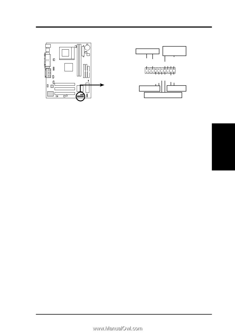
3. H/W SETUP Connectors 3. HARDWARE SETUP The following 20-pin PANEL illustration is for items 12-16. Power LED Speaker Connector PLED+ PLED+5V Ground Ground Speaker ExtSMI# Ground PWR GND Reset Ground CUVL-VM CUVL-VM System Panel Connectors SMI Lead Reset SW ATX Power Switch* * Requires an ATX power supply. 12) System Power LED Lead (3-1 pin PWR.LED) This 3-1 pin connector connects to the system power LED. The LED lights up when you turn on the system power, and blinks when the system is in sleep or soft-off mode. 13) System Warning Speaker Lead (4-pin SPEAKER) This 4-pin connector connects to the case-mounted speaker and allows you to hear system beeps and warnings. 14) System Management Interrupt Lead (2-pin SMI) This 2-pin connector allows you to manually place the system into a suspend mode, or "Green" mode, where system activity is instantly decreased to save power and to expand the life of certain system components. Attach the casemounted suspend switch this 2-pin connector. 15) ATX Power Switch / Soft-Off Switch Lead (2-pin PWR.SW) The system power is controlled by a momentary switch attached to this connector. Pressing the button switches the system between ON and SLEEP, or ON and SOFT OFF, depending on the BIOS or OS settings. Pressing the button while in the ON mode for more than 4 seconds turns the system off. 16) Reset Switch Lead (2-pin RESET) This 2-pin connector connects to the case-mounted reset switch for rebooting the system without turning off the power switch. This is a preferred method. ASUS CUVL-VM User's Manual 35
-
 1
1 -
2
-
3
-
4
-
5
-
6
-
7
-
8
-
9
-
10
-
11
-
12
-
13
-
14
-
15
-
16
-
17
-
18
-
19
-
20
-
21
-
22
-
23
-
24
-
25
-
26
-
27
-
28
-
29
-
 30
30 -
 31
31 -
 32
32 -
 33
33 -
 34
34 -
 35
35 -
 36
36 -
 37
37 -
 38
38 -
 39
39 -
 40
40 -
41
-
42
-
43
-
44
-
45
-
46
-
47
-
48
-
49
-
50
-
51
-
52
-
53
-
54
-
55
-
56
-
57
-
58
-
59
-
60
-
61
-
62
-
63
-
64
-
65
-
66
-
67
-
68
-
69
-
70
-
71
-
72
-
73
-
74
-
75
-
76
-
77
-
78
-
79
-
80
-
81
-
82
-
83
-
84
-
85
-
86
 |
 |